Toshiba B-570 SERIES User Manual
Page 81
3-4
EM18-33010A
3. INSTALLATION PROCEDURE FOR THE OPTIONAL EQUIPMENT
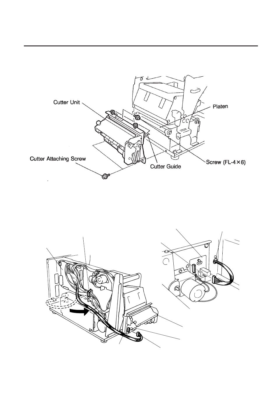
Fig. 3-5
Fig. 3-6
3.2 CUTTER MODULE (B-4205-QM)
7.
Install the cutter unit with the attached screws (cutter attaching screw, FL-4x6).
When installing the cutter, make sure that the cutter guide is not in contact with the platen. If it is, print
failure or noise may be caused.
8.
Remove the motor cover. (See Fig. 2-9.)
9.
Disconnect the connector from CN2 on the PWM PC board.
Clamp and pass the cable through the opening and connect it to the CN1 on the Cutter I/F PC board.
Clamp
CPU PC Board
Connector (CN2)
PWM PC Board
Opening
Cable
Cut I/F PC Board
Cutter Unit
Connector (CN2)
SVO7A1003: Nov. 21 ’97
See also other documents in the category Toshiba Printers:
- e-STUDIO222cp (16 pages)
- e-STUDIO382p (22 pages)
- Copier (78 pages)
- e-Studio Imaging 5520c (288 pages)
- multifunctional digital color systems e-STUDIO4540C (282 pages)
- B-852 Advance (2 pages)
- GA-1121 (118 pages)
- 720T (8 pages)
- 305 (168 pages)
- TEC EO1-32004 (94 pages)
- TEC DRJST-51 (19 pages)
- MULTIFUNCTIONAL DIGITAL COLOR SYSTEMS 2830C (178 pages)
- B-SP2D (50 pages)
- R-TH10 (86 pages)
- B-682-QP (157 pages)
- B-680-QQ (32 pages)
- e-STUDIO 281C (8 pages)
- TEC EO1-33027E (122 pages)
- MULTIFUNCTIONAL DIGITAL COLOR SYSTEMS e-STUDIO5520C (210 pages)
- 7FM03281000 (34 pages)
- B-570 (90 pages)
- GD-1270 (120 pages)
- ESTUDIO 230L (382 pages)
- 520 (7 pages)
- TEC EM1-33043D (46 pages)
- B-EP2DL (28 pages)
- TRST-A15 SERIES (31 pages)
- TEC B 452 (184 pages)
- TEC EO1-33016E (34 pages)
- B-670-QQ (34 pages)
- REMOTE RECEIPT PRINTER TRST-A00 (35 pages)
- e-STUDIO Printer/Fax/Scanner/Copier (4 pages)
- 282 (48 pages)
- B-480-QP (170 pages)
- B-450-QQ (28 pages)
- B-480-QQ (30 pages)
- B-SA4TP SERIES (114 pages)
- TEC EO1-13016 (24 pages)
- B-450-HS-QQ (34 pages)
- E.STUDIO 603 (216 pages)
- e-STUDIO 170F (244 pages)
- B-SA4 (2 pages)
- TEC EM1-33039E (34 pages)
- B-852 (2 pages)