Toshiba B-570 SERIES User Manual
Page 45
1-9
1. OUTLINE OF THE SYSTEM
EM10-33006A
Signal Name
DATA 1 ~ 8
INPUT•PRIME
DATA•STB
BUSY
FAULT
PAUSE
ACK
PE
2
Centronics interface
(1) Data input method:
8-bit parallel (DATA 1 ~ 8)
(2) Control signals:
ACK, BUSY, PAUSE, DATA;STB, INPUT; PRIME, FAULT, PE
(3) Data input code:
ASCII, JIS 8-bit code for European characters, 8-bit code for graphic
(4) Receiving buffer:
5KB
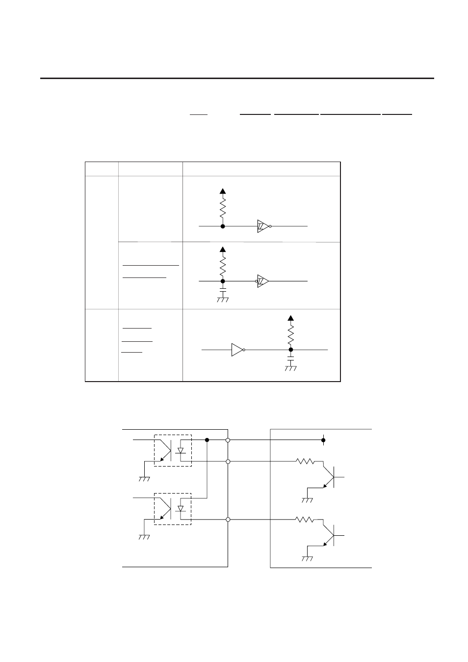
(5) Input/Output crcuit configuration and Input/Output conditions
1.5 ELECTORONICS SPECIFICATIONS
SN74LS14 or equivalent
SN74LS14 or equivalent
SN7406 or equivalent
1K
+5V
1K
+5V
+5V
100P
1K
100P
Type
Input
Output
Configuration
Logical level (input)
"1" = 2~5 V
"0" = 0~0.4 V
Logical level (input)
"1" = 2.4~5 V
"0" = 0~0.4 V
Fig. 1-7
3
External I/O interface
(1) Interface circuit
■
Input circuit
Fig. 1-8
There are five input circuits, and each input is a current loop using a photo-coupler. The anode of the
photo-coupler is connected to common pin COM1 in each of the five circuits. Each cathode is
independent. The voltage of Vcc is 24 V (max.) while the diode operating current is 16 mA.
External controller, etc.
Vcc
R
R
Photo-coupler
TPL521 (TOSHIBA)
COM1
IN0
IN4
~
~
Printer