5 display window overview and description, Display window overview and description 3-5 – Texas Instruments TMS370 User Manual
Page 55
Display Window Overview and Description
3-5
3.5
Display Window Overview and Description
The
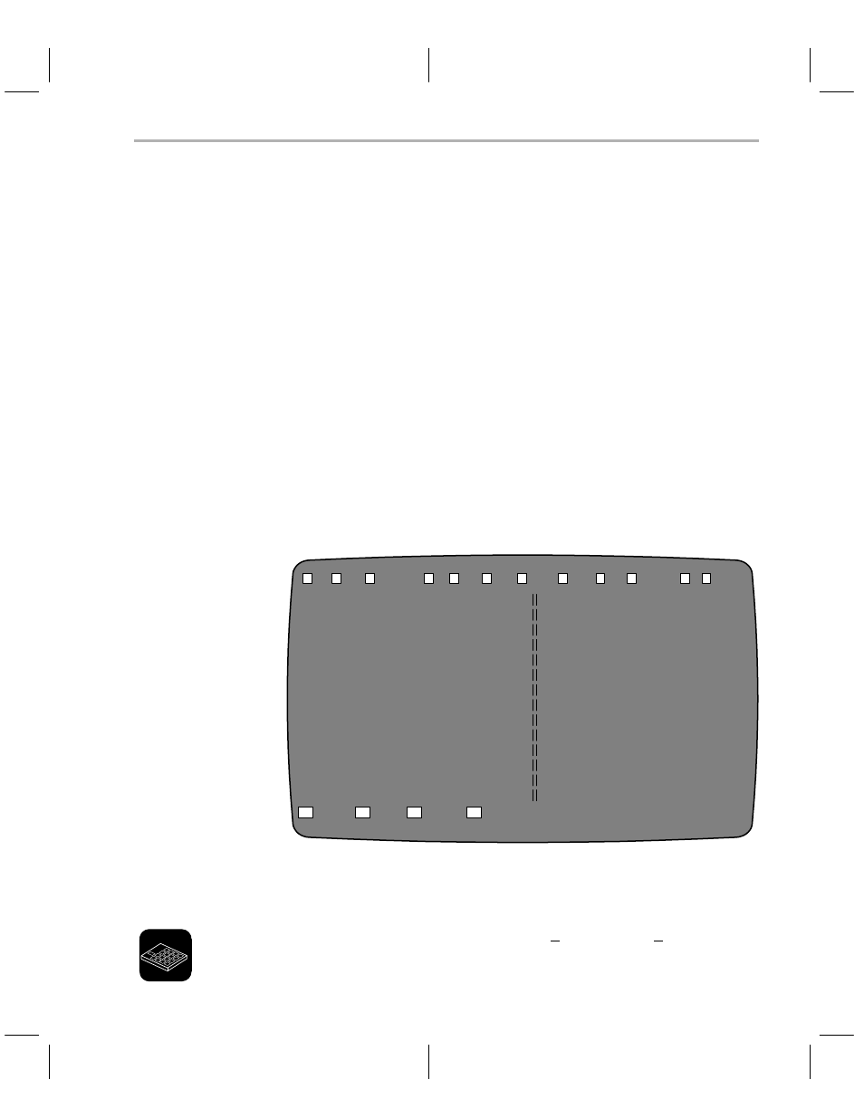
display window has two separate areas (see Figure 3–2): the PC
memory display (left half of screen) and the reverse assembled code (right half
of screen).
The programmer displays the PC memory in a hexadecimal format. The
memory address occupies the left-most column of each line, followed by eight
bytes of PC memory contents. Next on the display line are eight characters that
represent the PC memory contents as ASCII values. Nonprintable ASCII char-
acters are represented by the . character.
The address range for the PC memory is from 0000h to FFFFh. Access to the
PC memory out of this range is not allowed. The programmer maintains the
array as a circular buffer so that any scrolling that exceeds the limits is wrapped
around.
The reverse-assembled code window contains the disassembled code from
the PC memory.
Figure 3–2. PC Memory Display and Reverse Assembled Code Windows
F
L
O
M
P
S
U
V
E
C
0000
00
00
00
00
00
00
00 00
........
0000
0000
JMP
0002
0008
00
00
00
00
00
00
00 00
........
0002
0000
JMP
0004
0010
00
00
00
00
00
00
00 00
........
0004
0000
JMP
0006
0018
00
00
00
00
00
00
00 00
........
0006
0000
JMP
0008
0020
00
00
00
00
00
00
00 00
........
0008
0000
JMP
000A
0028
00
00
00
00
00
00
00 00
........
000A
0000
JMP
000C
0030
00
00
00
00
00
00
00 00
........
000C
0000
JMP
000E
0038
00
00
00
00
00
00
00 00
........
000E
0000
JMP
0010
0040
00
00
00
00
00
00
00 00
........
0010
0000
JMP
0012
0048
00
00
00
00
00
00
00 00
........
0012
0000
JMP
0014
0050
00
00
00
00
00
00
00 00
........
0014
0000
JMP
0016
0058
00
00
00
00
00
00
00 00
........
0016
0000
JMP
0018
0060
00
00
00
00
00
00
00 00
........
0018
0000
JMP
001A
0068
00
00
00
00
00
00
00 00
........
001A
0000
JMP
001C
0070
00
00
00
00
00
00
00 00
........
001C
0000
JMP
001E
0078
00
00
00
00
00
00
00 00
........
001E
0000
JMP
0020
0080
00
00
00
00
00
00
00 00
........
0020
0000
JMP
0022
0088
00
00
00
00
00
00
00 00
........
0022
0000
JMP
0024
0090
00
00
00
00
00
00
00 00
........
0024
0000
JMP
0026
0098
00
00
00
00
00
00
00 00
........
0026
0000
JMP
0028
00A0
00
00
00
00
00
00
00 00
........
0028
0000
JMP
002A
ill
oad
utputCOFF
ove
rogm
how
pload
erify
dit
onfig
s s
uit
PgDown
PgUp
Address
DisAsm
F1
F2
F3
F4
Current Device: TMS370 C256
PCMODE
Y
Q
All the commands are described briefly in Table 3–2. A complete description
of all display window commands can be found in Sections 3.6 through 3.17.
When you use the gang programmer, the BlankChk and mAster options are
added to the command line.