Texas Instruments TMS370 User Manual
Page 25
Properly Installing the Programmer Hardware
1-11
1.3.5
Integrated Circuit (IC) Insertion
ICs may be inserted or removed while power is applied to the programmer;
however:
1) When using the microcontroller programmer, never use
more than one IC socket at a time. Damage to the IC or the
programmer could result.
2) Never insert or remove the IC while the red LED is on. Dam-
age to the IC or the programmer could result.
3) TMS devices contain circuits to protect their inputs and out-
puts against damage due to electrostatic discharges of up to
2 kV. However, you should employ the usual precautions
when handling MOS devices, such as storing the device in
conductive foam and grounding yourself when handling
them.
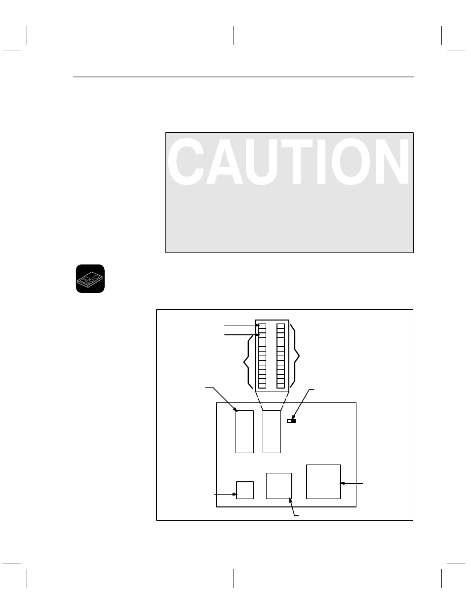
For the microcontroller programmer, decide which of the sockets (U1, U2, U3,
U4, or U5) to use for your device. Figure 1–3, shows the circuit board and IC
sockets.
Figure 1–3. Socket Identification
U1
U2
U3
U4
U5
370Cx10 DIP
370Cx10 PLCC
J2
Set to left for 2732
Set to right for 2764, 27128,
and 27256
{
pin 1
2764, 27128, and 27256
pin 1
2732 pin 1
2732
2764
27128
27256
370Cx5x PLCC
370Cx32 PLCC