Texas Instruments TMS370 User Manual
Page 26
Properly Installing the Programmer Hardware
1-12
Introduction and Installation
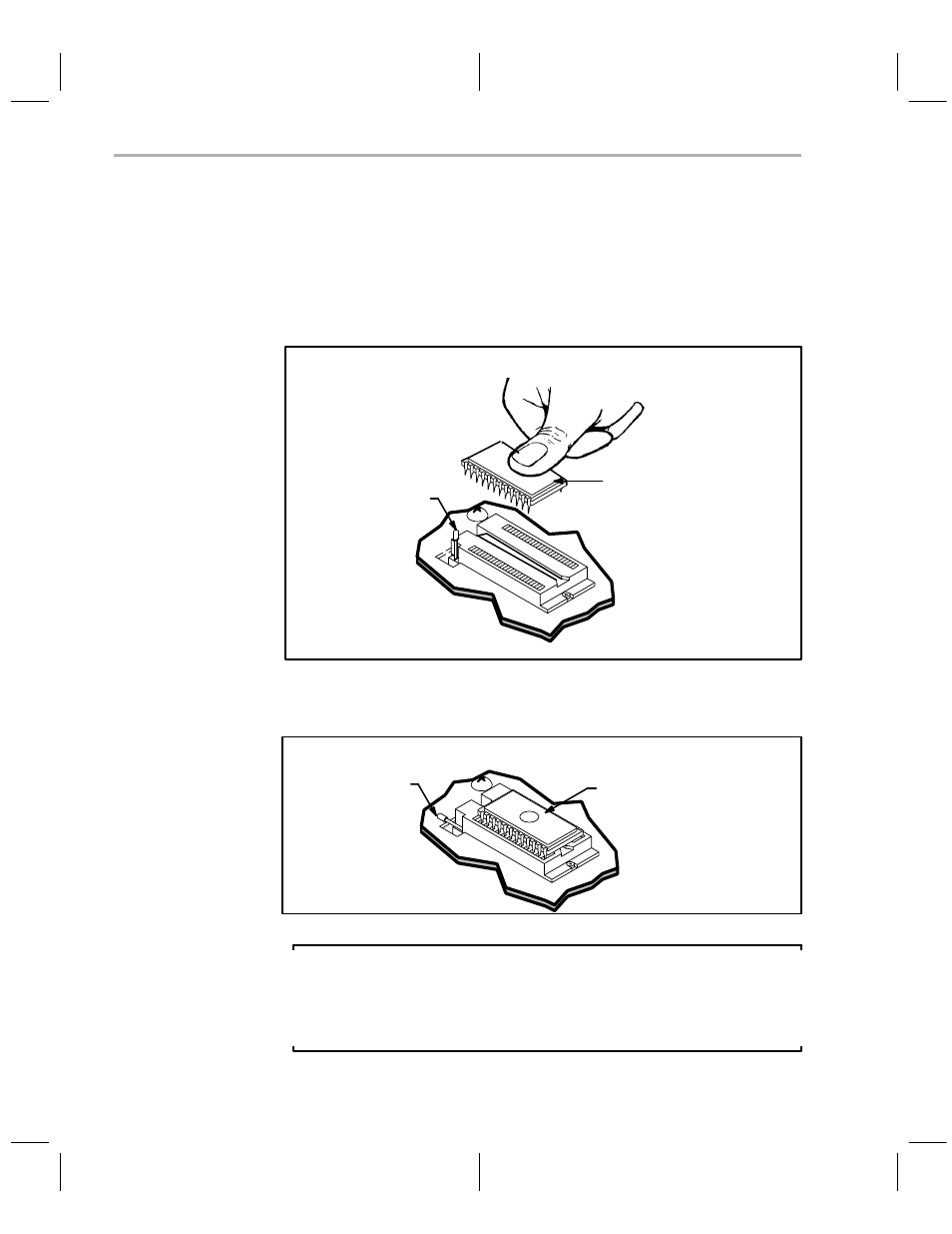
To install a DIP device:
1) Align the IC so that pin 1 is oriented in the upper-left corner, indicated on
the printed circuit board by a circled number 1:
2) Raise the locking arm, pulling it toward you to the upright position.
3) Insert the IC.
locking arm
DIP
4) Lower the locking arm by pushing it away from you and down, as far as
it will go.
locking arm
DIP
Note:
If you install a 2732 device in U2, be sure to use the bottom socket holes,
leaving the top four socket holes unused. The correct position for a 2732
is indicated by a bracket on the printed circuit board to the left of the socket.
See also other documents in the category Texas Instruments Hardware:
- Digital Signal Processor SM320F2812-HT (153 pages)
- MSP430x1xx (440 pages)
- Laser And Motor Drives DRV8811EVM (13 pages)
- TMS320 DSP (88 pages)
- MSP430x11x1 (45 pages)
- TVP5154EVM (55 pages)
- TMS320DM646X DMSOC (64 pages)
- CC2511 (24 pages)
- SN65HVS880 (4 pages)
- TPS650231EVM (14 pages)
- TMS320TCI648x (256 pages)
- TSC2007EVM-PDK (16 pages)
- UCC38500EVM (16 pages)
- TMS320C6000 (62 pages)
- SCAU020 (21 pages)
- TPS40051 (17 pages)
- TNETE2201 (14 pages)
- TMS320C64x DSP (306 pages)
- UCC2891 (21 pages)
- TMS320C3x (757 pages)
- MSP430 (138 pages)
- TMS320C6712D (102 pages)
- MSP430x4xx (512 pages)
- TMS320C6454 (225 pages)
- SPRU938B (48 pages)
- TUSB3210 (22 pages)
- TMS320C6457 (43 pages)
- CC2530ZNP (3 pages)
- TMS320C6455 (50 pages)
- TSB12LV26 (91 pages)
- TMS320C6472 (2 pages)
- VLYNQ Port (49 pages)
- TMS380C26 (92 pages)
- MSP-FET430 (95 pages)
- TMS320TCI6486 (160 pages)
- TPS2330 (22 pages)
- DM648 DSP (47 pages)
- TMS320DM36X (134 pages)
- MSC1211 (35 pages)
- SPRAA56 (29 pages)
- DAC7741EVM (28 pages)
- CDCM7005 (34 pages)
- Adpater (37 pages)
- TMS320C6452 DSP (46 pages)