Figure 2–3. the show ranges window, Table 2–3. show ranges parameter summary – Texas Instruments TMS370 User Manual
Page 41
Secondary Configuration Window—the Show Ranges Window
2-7
2.6
Secondary Configuration Window—the Show Ranges Window
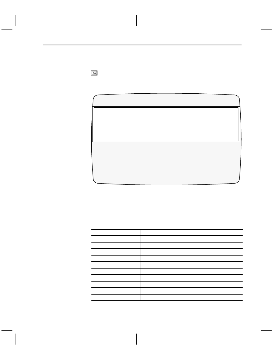
A small subwindow appears when you select the
show ranges function key,
, from the device area of the configuration window. Figure 2–3 illustrates
what the show ranges
window looks like.
Figure 2–3. The Show Ranges Window
ChooseDevice
CONFIG:
Program Configuration
Port#: 1
Device
Type
27128
TMS27C128
27256
TMS27C256
2732
TMS2732A
2764
TMS2764
TMS27C64
7742
TMS7742
TMS370
16K_PE
256_DEE
4K_PE
512_DEE
C010
C050
Valid address ranges for 2732/TMS2732A
START
SIZE
TYPE
Vcc
Vpp
Pdt
CtrlReg
FmlyCode
BlkErase
Pbits
00000h
1000h
EPROM
5
21
10
ooh
40h
NO
O’s only
The show ranges window does not neccesarily default to show the ranges of
the chosen device. Instead, it shows the ranges of the device that the cursor
is next to in the device table. You can scroll through the device table and notice
the parameters changing in accordance with each new device the cursor is
next to.
Table 2–3. Show Ranges Parameter Summary
Parameter
Description
Start
Valid start address for programming.
Size
Size of the valid program area.
Type
The type of memory in this range (EEPROM or EPROM).
VCC
Valid Vcc values are 0, 5, or 6 volts.
VPP
Valid Vpp values are 0, 5, 12, 12.5 or 21 volts.
pdt
Program pulse duration time.
ctrlReg
The control register.
FmlyCode
The hexadecimal family code of the device.
Blk-Erase
The block erase toggle.
Pbits †
The program algorithm.
†
The program algorithms are discussed in detail in subsection 2.6.1.