Appendix – Transition Networks SISGM1040-162D User Manual
Page 125
Transition Networks
SISGM1040-162D-LR
118
Appendix
10 /100BASE-TX Pin outs
With10/100BASE-TX cable, pins 1 and 2 are used for transmitting data, and pins 3 and 6
for receiving data.
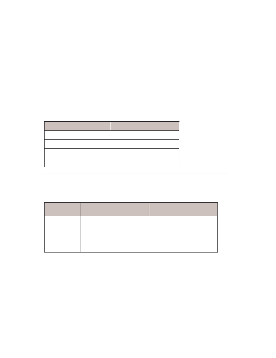
RJ-45 Pin Assignments
Pin Number
Assignment
1
Tx+
2
Tx-
3
Rx+
6
Rx-
[NOTE] “+” and “-” signs represent the polarity of the wires that make up each wire pair.
The table below shows the 10 / 100BASE-TX MDI and MDI-X port pin outs.
Pin MDI-X
Signal Name
MDI Signal Name
1
Receive Data plus (RD+)
Transmit Data plus (TD+)
2
Receive Data minus (RD-)
Transmit Data minus (TD-)
3
Transmit Data plus (TD+)
Receive Data plus (RD+)
6
Transmit Data minus (TD-)
Receive Data minus (RD-)
10/100Base-TX Cable Schematic
The following two figures show the 10/100Base-TX cable schematic.