NEC uPD78P078 User Manual
Page 186
186
CHAPTER 8 16-BIT TIMER/EVENT COUNTER
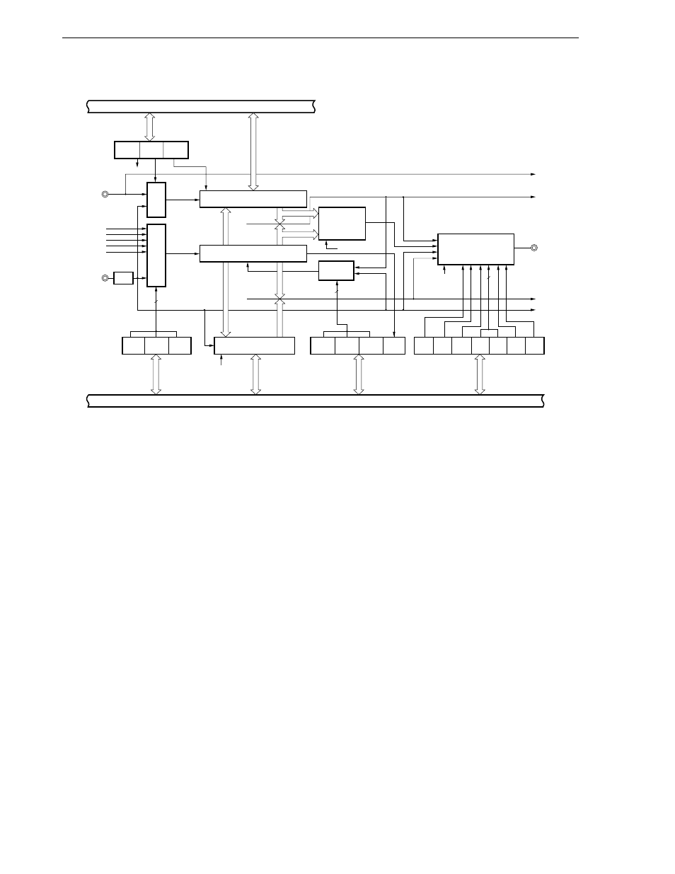
Figure 8-1. 16-Bit Timer/Event Counter Block Diagram
Notes 1. Edge detection circuit
2. The configuration of the 16-bit timer/event counter output control circuit is shown in Figure 8-2.
Internal bus
Capture/Compare
Control Register 0
CRC02 CRC01 CRC00
Selector
TI01 /
P01 /
INTP1
INTTM3
2f
XX
f
XX
f
XX
/2
f
XX
/2
2
TI00 /
P00 /
INTP0
Selector
3
TCL06 TCL05 TCL04
Timer Clock
Selection
Register 0
CRC02
16-Bit Capture/Compare
Control Register (CR01)
Internal Bus
16-Bit Capture/Compare
Control Register (CR00)
16-Bit Timer Register (TM0)
Clear
Match
Clear
Circuit
TMC03 TMC02 TMC01 OVF0
OSPT OSPE TOC04 LVS0 LVR0 TOC01 TOE0
16-Bit Timer
Mode Control
Register
16-Bit Timer Output
Control Register
2
PWM Pulse
Output
Control
16-Bit Timer/Event
Counter Output
Control Circuit
Note 2
TMC01 to
TMC03
INTP0
INTTM01
TO0/P30
INTP1
INTTM00
Match
TMC01 to TMC03
3
Note 1