Helical arcs, Figure 6-10. helical arc, Helical arcs -13 – National Instruments NI-Motion User Manual
Page 91
Chapter 6
Arc Moves
© National Instruments Corporation
6-13
//Get the command ID, resource ID, and the
error code of the //modal error from the
error stack on the device
flex_read_error_msg_rtn
(boardID,&commandI
D,&resourceID, &errorCode);
nimcDisplayError(errorCode,commandID,res
ourceID);
//Read the communication status register
flex_read_csr_rtn
(boardID,&csr);
}while(csr & NIMC_MODAL_ERROR_MSG);
}
else
// Display regular error
nimcDisplayError(err,0,0);
return
;// Exit the Application
}
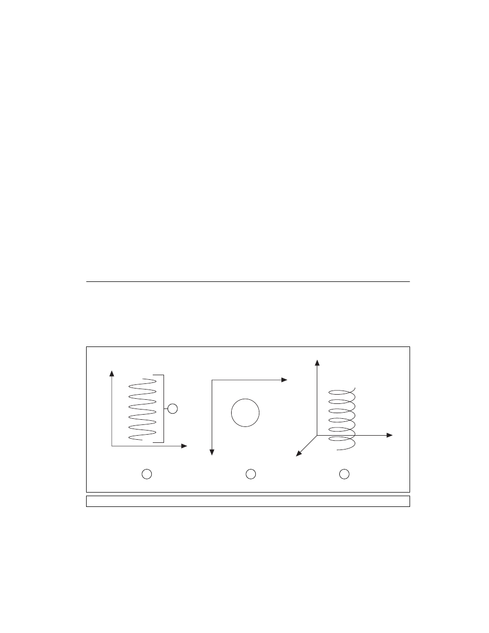
Helical Arcs
A helical arc defines an arc in a 3D coordinate space that consists of a circle
in the XY plane and synchronized linear travel in the Z-axis. The arc is
specified by a radius, start angle, travel angle, and Z-axis linear travel.
Linear travel is the linear distance traversed by the helical arc on the Z-axis,
as shown in Figure 6-10.
Figure 6-10. Helical Arc
1
Side View of Helix
2
Top View of Helix
3
Isometric View of Helix
4
Linear Travel
X
Y
Z
X
Y
X
Z
1
2
3
4