Figure 10-13. gear ratio change, Figure 10-14. camming cycle repeats, Slave offset – National Instruments NI-Motion User Manual
Page 137: Slave offset -15
Chapter 10
Electronic Gearing and Camming
© National Instruments Corporation
10-15
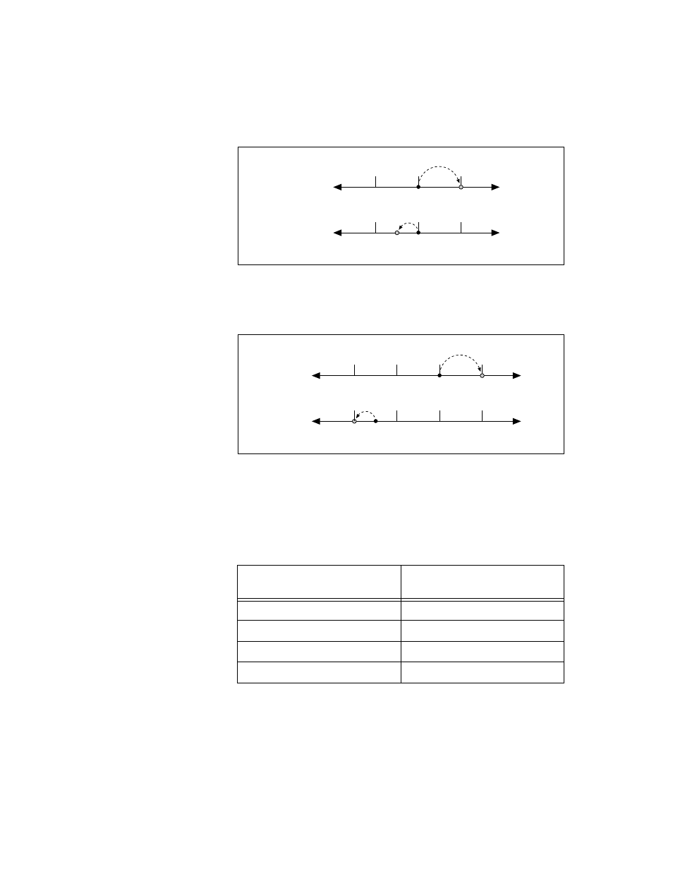
Figure 10-13. Gear Ratio Change
Figure 10-14 shows that when the master reaches position 6000, the slave
axis moves back the original position, and the camming cycle begins again.
Figure 10-14. Camming Cycle Repeats
Slave Offset
In some camming applications, the slave axis might begin and end the
camming cycle at different positions, as shown in Table 10-2.
Table 10-2. Camming Profile with and without Slave Offset
Master Position
(counts)
Slave Position
(counts)
0
0
2000
2000
4000
1000
6000
500
0
2000
Master
0
2000
1000
4000
4000
Slave
0
2000
Master
0
2000
1000
4000
4000
6000
6000
Slave