Figure 6 . main elements of the ups system – Powerware 9330 User Manual
Page 76
6--2
Powerware 9330 (10 kVA--40 kVA) Installation and Operation
164201300 REV. G 061502
DIGITAL
AC INPUT TO
AC INPUT TO
AC OUTPUT
INPUT
RECTIFIER
INVERTER
FILTER
METERING
RECTIFIER/
BYPASS
TO CRITICAL
STATIC
SWITCH
CHARGER
LOAD
OUTPUT
FILTER
INPUT
BATTERY
BREAKER
CB2
BREAKER
CB1
POWER PROCESSING UNIT
UPS CABINET
INPUT
CONTACTOR
BATTERY
CONVERTER
DC--DC
OUTPUT
CONTACTOR
BATTERY
SWITCHES
BATTERY
CHARGER
CONTACTOR
BACKFEED
PROTECTION
K1
K3
K5
MAINTENANCE
BYPASS SWITCH
BOOST
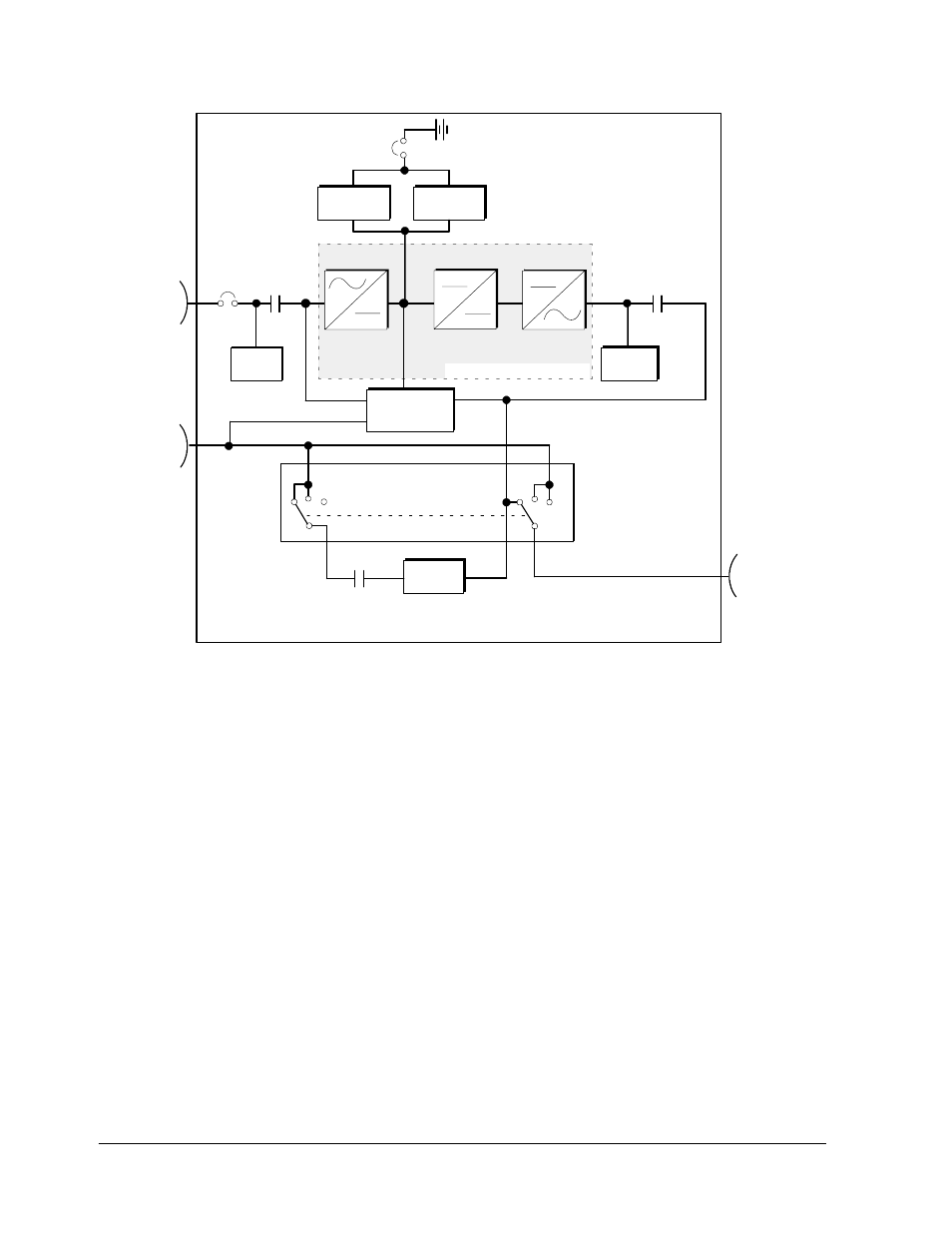
Figure 6---1. Main Elements of the UPS System
If utility power is interrupted or falls outside the parameters specified in Chapter 15,
“Product Specifications,” the UPS uses a
backup battery supply to maintain power
to the critical load for a specified period of time or until the utility power returns.
For extended power outages, the UPS allows you to either transfer to an alternative
power system (such as a generator) or shut down your critical load in an orderly
manner.
The emergency bypass consist of a continuous duty static switch, and backfeed
protection contactor (K5). The backfeed protection contactor is located in series
with the static switch. For manual transfers to bypass, the static switch is also
used. The static switch is armed and ready during both types of transfers.
A wraparound Maintenance Bypass switch provides a means of isolating the UPS
Power Processsing Unit (PPU) for servicing, while still suppling power to the critical
load.
The operation of the UPS system is described in greater detail in the following
paragraphs.