Ab c d – Powerware 9330 User Manual
Page 177
DESCRIPTION:
DATE:
DRAWING NO:
6 of 17
SHEET:
REVISION: G
NOTE:
Callout letter
and
map to drawing #164201300---6
,
, ,
061502
A
B
C
D
164201300---1
POWER WIRING INSTALLATION NOTES
A
B
C
D
A---7
Powerware 9330 (10 kVA--40 kVA) Installation and Operation
164201300 REV. G 061502
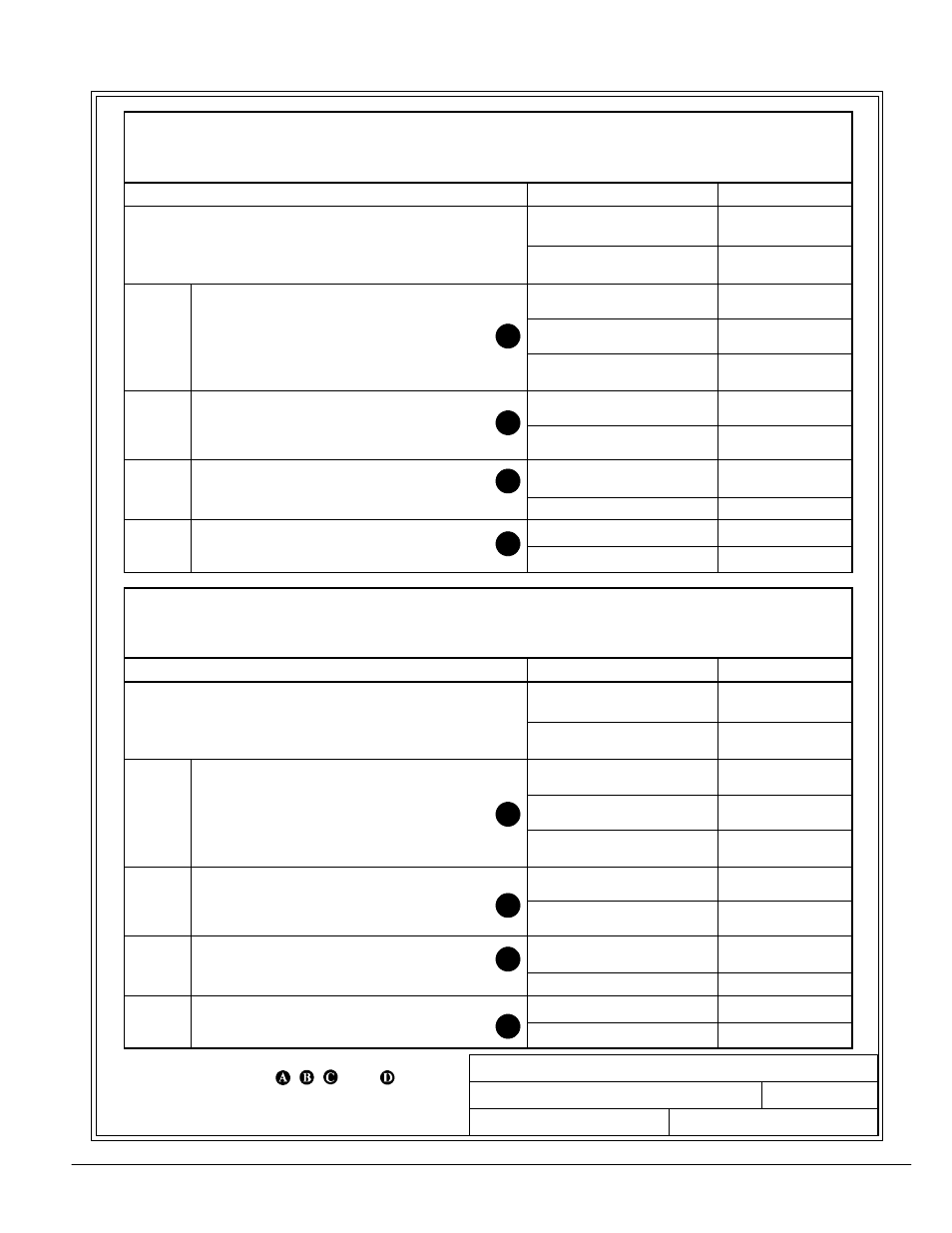
Table I. INPUT/OUTPUT Ratings & External Wiring Requirements for
Powerware 9330---40/35
(Without Options Cabinet)
Ratings
Units
Rating 50/60 Hz
Basic unit ratings at
0.7 lagging PF load
KVA
KW
35
24.5
gg g
INPUT/OUTPUT
VOLTAGE
208
AC Input to UPS Rectifier
(0.95min.PF)
Amps*
92
AC
AC Input to UPS Rectifier
(0.95min.PF)
3 , 1 gnd
Amps*
92
AC
INPUT
3 , 1 gnd
Minimum conductor size (number per )
AWG or kcmil(ea)
2 (1)
*(Maximum amps includes full load current plus
battery recharge current)
AC
AC Input to Module Bypass (UPS Bypass)
Full Load Current
3 , (1) Neutral, (1) gnd
Amps
97
AC
INPUT
Full Load Current
3 , (1) Neutral, (1) gnd
Minimum conductor size (number per )
AWG or kcmil(ea)
1 (1)
DC
INPUT
DC Input from External Battery Source to UPS
(1) positive, (1) negative, (1) gnd
VDC (Nominal)
Amps
288
91
INPUT
( ) pos t e, ( ) egat e, ( ) g d
Minimum conductor size (number per pole) (See note 8)
AWG or kcmil(ea)
2 (1)
AC
AC Output to Critical Load
Full Load Current 3 (1) Neutral (1) gnd
Amps
97
AC
OUTPUT
Full Load Current 3 , (1) Neutral, (1) gnd
Minimum conductor size (number per )
AWG or kcmil(ea)
1 (1)
Table J. INPUT/OUTPUT Ratings & External Wiring Requirements for
Powerware 9330---40/40
(Without Options Cabinet)
Ratings
Units
Rating 50/60 Hz
Basic unit ratings at
0.7 lagging PF load
KVA
KW
40
28
gg g
INPUT/OUTPUT
VOLTAGE
208
AC Input to UPS Rectifier
(0.95min.PF)
Amps*
100
AC
AC Input to UPS Rectifier
(0.95min.PF)
3 , 1 gnd
Amps*
100
AC
INPUT
3 , 1 gnd
Minimum conductor size (number per )
AWG or kcmil(ea)
1 (1)
*(Maximum amps includes full load current plus
battery recharge current)
AC
AC Input to Module Bypass (UPS Bypass)
Full Load Current
3 , (1) Neutral, (1) gnd
Amps
111
AC
INPUT
Full Load Current
3 , (1) Neutral, (1) gnd
Minimum conductor size (number per )
AWG or kcmil(ea)
2/0 (1)
DC
INPUT
DC Input from External Battery Source to UPS
(1) positive, (1) negative, (1) gnd
VDC (Nominal)
Amps
288
100
INPUT
( ) pos t e, ( ) egat e, ( ) g d
Minimum conductor size (number per pole) (See note 8)
AWG or kcmil(ea)
1 (1)
AC
AC Output to Critical Load
Full Load Current 3 (1) Neutral (1) gnd
Amps
111
AC
OUTPUT
Full Load Current 3 , (1) Neutral, (1) gnd
Minimum conductor size (number per )
AWG or kcmil(ea)
2/0 (1)