Powerware 9330 User Manual
Page 180
DESCRIPTION:
DATE:
DRAWING NO:
9 of 17
SHEET:
REVISION: F
111501
NOTE: Customer ground, size 1/0, can be
run in any conduit listed in Table R.
POWER WIRING INSTALLATION NOTES
164201300---1
A---10
Powerware 9330 (10 kVA--40 kVA) Installation and Operation
164201300 REV. G 061502
9.
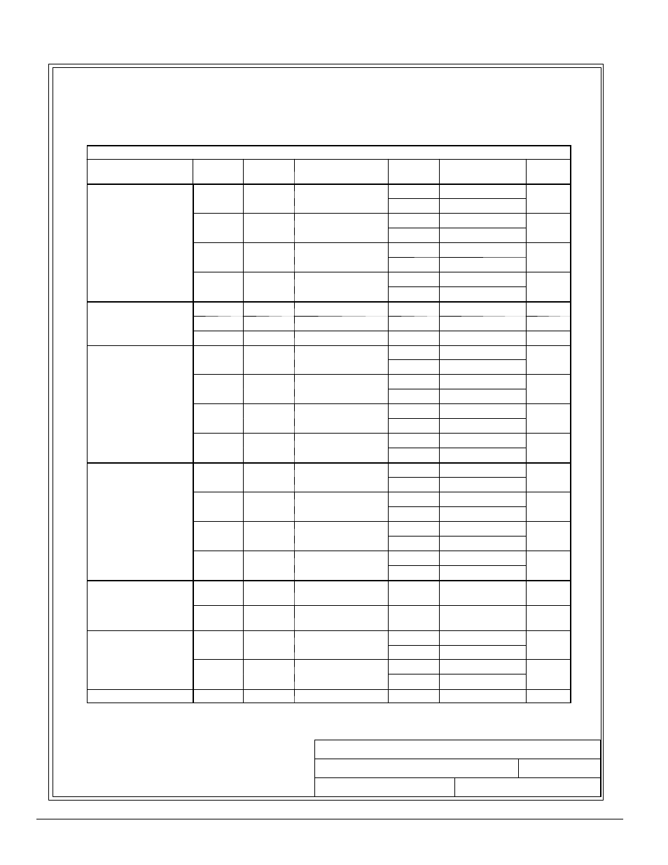
Terminals are UL and CSA rated at 90˚C. Refer to Tables N through Q for power cable
terminations, and Table R and U for conduit requirements. Drawings 164201300---8
through 164201300---12 show the location of the power cable terminals inside the UPS,
Options, and Battery Cabinets.
Table N. UPS Cabinet Power Cable Terminations Powerware 9330 (10 kVA---20 kVA)
Terminal Function
Terminal
Function
Size of Pressure
Termination
Vendor
Tightening Torque
N-M (lb-in.)
Type
Screw
AC Input to UPS
A
Phase A 1
#14 #4
Entrelec
1.3-1.4 (11-12)
Slotted
p
Rectifier and Bypass
(TB2)
A
Phase A 1 --- #14---#4
Phoenix
1.5-1.8 (13-16)
Slotted
(TB2)
(Single Input)
B
Phase B 1
#14 #4
Entrelec
1.3-1.4 (11-12)
Slotted
(Single Input)
B
Phase B 1 --- #14---#4
Phoenix
1.5-1.8 (13-16)
Slotted
C
Phase C 1
#14 #4
Entrelec
1.3-1.4 (11-12)
Slotted
C
Phase C 1 --- #14---#4
Phoenix
1.5-1.8 (13-16)
Slotted
N
Neutral
1
#4 #0
Entrelec
2.5-2.9(22-26)
Slotted
N
Neutral
1 --- #4---#0
Phoenix
3.2-3.7(28-33)
Slotted
AC Input to UPS
C
A
Phase A 1 --- #18---#2
N/A
2.0 (17.5)
Phillips
p
Rectifier (CB1)
(Dual Input)
B
Phase B 1 --- #18---#2
N/A
2.0 (17.5)
Phillips
(Dual Input)
C
Phase C 1 --- #18---#2
N/A
2.0 (17.5)
Phillips
AC Input To Bypass
A
Phase A 1
#14 #4
Entrelec
1.3-1.4 (11-12)
Slotted
p
yp
(TB2)
(Dual Input)
A
Phase A 1 --- #14---#4
Phoenix
1.5-1.8 (13-16)
Slotted
(Dual Input)
B
Phase B 1
#14 #4
Entrelec
1.3-1.4 (11-12)
Slotted
B
Phase B 1 --- #14---#4
Phoenix
1.5-1.8 (13-16)
Slotted
C
Phase C 1
#14 #4
Entrelec
1.3-1.4 (11-12)
Slotted
C
Phase C 1 --- #14---#4
Phoenix
1.5-1.8 (13-16)
Slotted
N
Neutral
1
#4 #0
Entrelec
2.5-2.9(22-26)
Slotted
N
Neutral
1 --- #4---#0
Phoenix
3.2-3.7(28-33)
Slotted
AC Output to Critical
A
Phase A 1
#14 #4
Entrelec
1.3-1.4 (11-12)
Slotted
p
Load
(Part of TB3)
A
Phase A 1 --- #14---#4
Phoenix
1.5-1.8 (13-16)
Slotted
(Part of TB3)
B
Phase B 1
#14 #4
Entrelec
1.3-1.4 (11-12)
Slotted
B
Phase B 1 --- #14---#4
Phoenix
1.5-1.8 (13-16)
Slotted
C
Phase C 1
#14 #4
Entrelec
1.3-1.4 (11-12)
Slotted
C
Phase C 1 --- #14---#4
Phoenix
1.5-1.8 (13-16)
Slotted
N
Neutral
1
#4 #0
Entrelec
2.5-2.9(22-26)
Slotted
N
Neutral
1 --- #4---#0
Phoenix
3.2-3.7(28-33)
Slotted
DC Input from
Battery to UPS
N/A
Battery
(+)
Red Battery
Connector
N/A
N/A
N/A
atte y to U S
N/A
Battery
(---)
Black Battery
Connector
N/A
N/A
N/A
External Battery
S
Battery
Positive
1
#14 #0
Entrelec
2.5-2.9(22-26
)
Slotted
y
Input to UPS
(Part of TB3)
y
+
Positive
1 --- #14---#0
Phoenix
3.2-3.7(28-33)
Slotted
(Part of TB3)
Battery
Negative 1
#14 #0
Entrelec
2.5-2.9(22-26)
Slotted
y
---
Negative 1 --- #14---#0
Phoenix
3.2-3.7(28-33)
Slotted
Customer Ground
Ground
Ground
2 --- #14---#1/0
N/A
5.6 (50)
Slotted