Temperature input, Thermocouple rtd 2-wire rtd 3-wire – Perle Systems 5500161-40 User Manual
Page 388
Wiring I/O Diagrams
388
IOLAN SDS/SCS/STS/MDC User’s Guide, Version 4.0
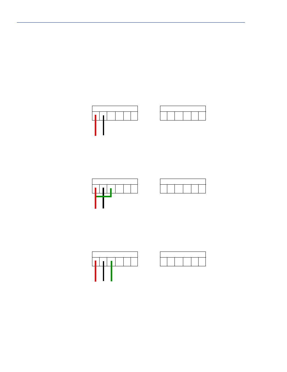
Temperature Input
If you are using RTD sensors, a short detected status will be displayed if the wires are connected
improperly. RTD or thermocouple sensors will display an open detection status when the circuit is
broken.
Thermocouple
To connect to Channel A1 with a 2-wire cable, connect the positive wire to A1+ and the negative
wire to A1-; you will not be using the A1s connection.
A1+
A1-
A1s
A2s
A2+
A2-
A3
+
A3
-
A3
s
A4
s
A4
+
A4
-
+
-
RTD 2-Wire
In a 2-wire RTD configuration, connect the excite wire to A1-, the return wire to A1+, and jumper the
sense wire from A1s with a insulated wire going to A1+.
A1+
A1-
A1s
A2s
A2+
A2-
A3
+
A3
-
A3
s
A4
s
A4
+
A4
-
return
excite
sense
RTD 3-Wire
In a 3-wire RTD configuration, connect the return wire to A1+, the excite wire to A1-, and the sense
wire to A1s.
A1
+
A1
-
A1
s
A2
s
A2
+
A2
-
A3+
A3-
A3s
A4s
A4+
A4-
return
excite
sense