Analog input, Current voltage – Perle Systems 5500161-40 User Manual
Page 387
I/O Wiring Diagrams 387
Wiring I/O Diagrams
Analog Input
Make sure the Analog jumpers support the software setting; see Analog Input Module
for jumper settings.
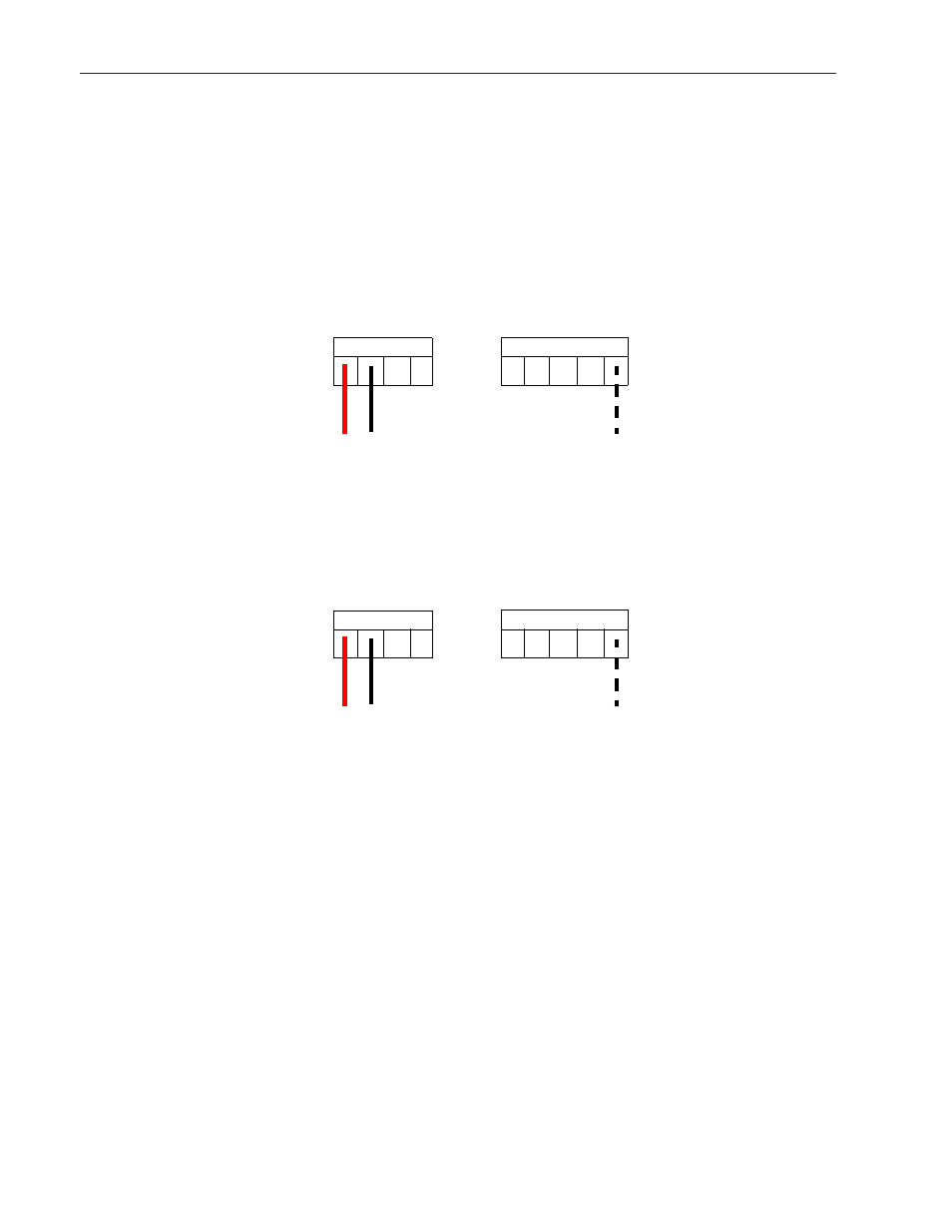
Current
To connect channel A1 with a 2-wire shielded cable, connect the positive wire to A1+, the negative
wire to A1-, and optionally the shield to GND.
A3
+
A3
-
A4
+
A4
-
GN
D
A1
+
A1
-
A2
+
A2
-
+
-
shield
If you have the positive/negative wires reversed, the output will always read 0 (zero).
Voltage
To connect to Channel A1 with a 2-wire shielded cable, connect the positive wire to A1+, the
negative wire to A1-, and optionally the shield to GND.
A3+
A3-
A4+
A4-
GND
A1
+
A1
-
A2
+
A2
-
+
-
shield
If you have the positive/negative wires reversed, the polarity of the voltage will be reversed.