Installation instructions – Sanyo DHX4852 User Manual
Page 40
2-30
Design of W-2WAY ECO-i SYSTEM Unit Specifications
1
2
3
4
5
6
7
8
1
2
3
4
5
6
7
8
1
2
3
4
5
6
7
8
1
2
3
4
5
6
7
8
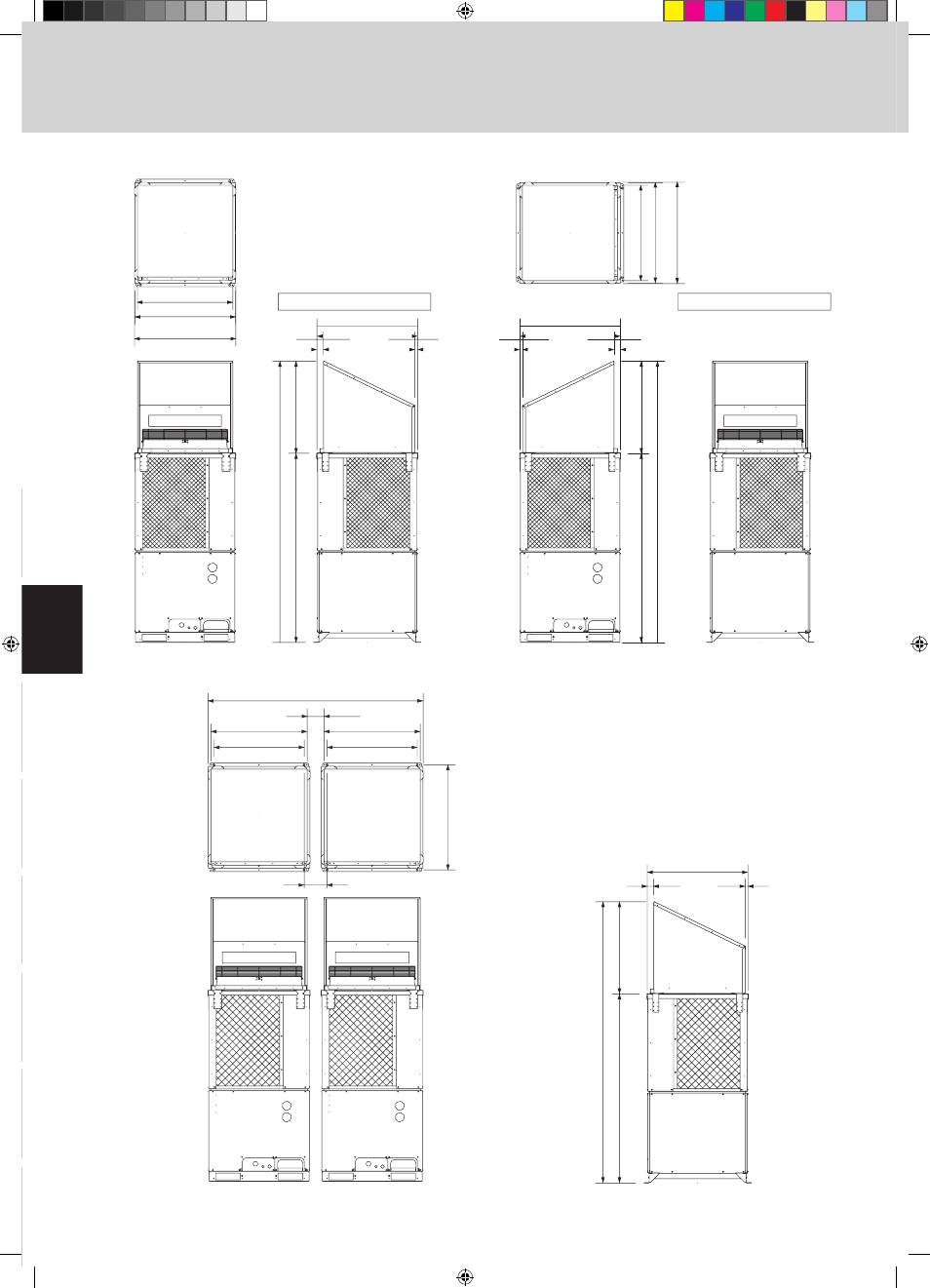
Reference diagram for air-discharge chamber (field supply)
4. Installation Instructions
33-3/16
2-11/64
15/16
97-29/32
65-53/64
(32-5/64)
35-15/64
(Maximum bracket dimensions)
35-3/64
(Ceiling panel dimensions)
33-3/16
35-15/64
(Maximum brac
ket dimensions)
35-3/64
(Ceiling panel dimensions)
35-3/64
(Ceiling panel dimensions)
2-11/64
15/16
97-29/32
65-53/64
(32-5/64)
35-3/64
(Ceiling panel dimensions)
Air direction: Front direction
Air direction: Right direction
Ceiling panel
Front view
Front view
Right side view
Right side view
Ceiling panel
unit: in.
Note: Can be installed so that the air direction is to the front, right, left or rear direction.
4-6. Dimensions of Wind Ducting
2-11/64
15/16
35-3/64
(Ceiling panel dimensions)
97-29/32
65-53/64
(32-5/64)
Right side view
unit: in.
31-7/64
33-3/16
5-25/32
74-7/32 (2-unit installation:maximum dimensions)
7-7/8
31-7/64
(Installation hole pitch)
33-3/16
36-7/32
(I
ns
ta
lla
tio
n
ho
le
p
itc
h)
Front view
Top view
2-unit installation
TD831138-02_W-2WAY.indb 30
2007/07/26 14:30:51