Outdoor unit, W-2way eco-i system unit specifications, 2. dimensional data – Sanyo DHX4852 User Manual
Page 121
4-7
W-2WAY ECO-i SYSTEM Unit Specifications
1
2
3
4
5
6
7
8
1
2
3
4
5
6
7
8
8hp
Refr
igerant (gas tube in (mm))
braz
ed
connectio
n
flare
d
connectio
n
flare
d
connectio
n
Refr
ig
er
an
t (
liqui
d tube in (mm)
)
Ref
rig
er
an
t (
balance
tube in (mm)
)
– 15
Wind direction
Wind direction
(Installation hole pitch)
(Top panel dimension)
(Max.)
(Bottom plate dimension)
(Bottom plate dimension)
Installation bracket mounting surf
ace
(Knoc
k-out hole)
(Knoc
k-out hole)
Refr
igerant (front:
knoc
kout hole and slit)
Tubing por
t (bottom:
hole with co
ver)
Electr
ical wir
ing por
t (front:
ш60, ш28 knoc
k-out holes – f
or conduit connection)
Electr
ical wir
ing por
t (bottom:
ш60, ш38 knoc
k-out holes – f
or conduit connection)
Pressure outlet po
rt (f
or high pressure:
ø7.94 Schrader-type connection
)
Pressure outlet po
rt (f
or lo
w pressure:
ø7.94 Schrader-type connection
)
Knoc
k-out hole f
or connecting pressure gauge (optional)
10hp
12hp
14hp
16hp
Left side
Right side
Fr
ont vi
ew
Installation holes (4
?
Top vi
ew
Z vi
ew
Space f
or creation of hole on-site (Max.
diameter ø1-57/64)
Si
ze
(mm)
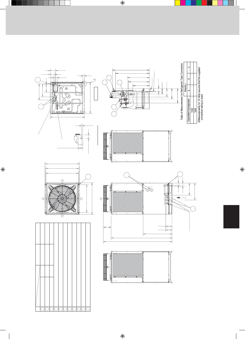
Ta
ble of Measurements f
or Refrigerant
Tube Connection
Holes used for transpor
t
∗
Measurements
for 10–16hp
assume that the supplied
connection tubing is used.
Equi
va
lent
horsepo
w
er
Enlar
ged vi
ew
of
A
6
8
4
11
5
7
×
20 elongated holes), anchor bolts M12 or larger
c
a
1
2
3
b
01
9
9-3/32
6-37/64
5-5/1
6
1-49/6
4
1-31/3
2
Refrigeran
t
12-61/64
21-1/16
22-7/8
4-39/64
(29/32)
1-31/32
37-13/32
36-7/32
35-3/64
(8-1/2)
65-25/32
31-19/64
6-15/16
6-11/32
74-19/64
1-31/32
3-15/16
5-1/8
37-13/32
17-51/64
(1-33/64)
31-7/64
(Installation hole pitch
)
35-3/64
(T
op panel dimension)
13-5/16
18 - 5/8
2-43/64
3-1
1/32
ш1-1/
2
ш2-23/64
34-9/64
14-1/4
9-1/16
13/64
Ref
riger
ant (gas tube in
. (mm)
)
ш7/8" (ш22.22
)
braz
ed
connectio
n
flare
d
connectio
n
flare
d
connectio
n
Refr
igerant
(liquid
tube in.
(mm)
)
Ref
rig
er
an
t (
balance
tube in
. (mm)
)
ш3/8" (ш9.52
)
ш1/4" (ш6.35
)
ш1-1/8" (ш28.58)
ш1/2" (ш12.70)
ш1/4" (ш6.35)
Refr
igerant (front:
knoc
k out hole and slit)
Tubing por (bottom:
hole with co
ve
r)
Electr
ical wir
ing por
t (front:
ш1-47/64", ш15/16", ш1-3/8" knoc
k-out holes – f
or conduit connection)
Electr
ical wir
ing por
t (bottom:
ш2 - 23/64", ш1-1/2" knoc
k-out holes – f
or conduit connection)
Pressure outlet po
rt (f
or high pressure:
ш5/16" (ш7.94) Schrader-type connection)
Pressure outlet po
rt (f
or lo
w pressure:
ш5/16" (ш7.94) Schrader-type connection)
Knoc
k-out hole f
or connecting pressure gauge (optional)
10hp
16hp
Installation holes (4–19/32"
×
25/32" elongated holes), anchor bolts M12 or 15/32" or larger
7-11/64
13-5/32
3-55/64
6-37/64
13-37/64
3-15/16
1
2
3
4
5
6
7
8
9
10
11
CHDX09053/14053
1. Outdoor Unit
1-2. Dimensional Data
TD831138-02_W-2WAY.indb 7
2007/07/26 14:32:19