System controller (sha-kc64ug), Test run, System examples – Sanyo CHX06052 User Manual
Page 79: Remote control functions
2-61
Remote Control Functions
4. System Controller (SHA-KC64UG)
2
5. Memory backup switch
Check the backup switch is ON for back side of system controller PCB.
6. Test run
(1)Power on for all indoor units. Next, power on for system controller.
will flash, checking the indoor unit address automatically.
(2)If GROUP No. displayed on system controller is not same as indoor UNIT
No.* which is connected, refer to “3. Mode Setting” and set again.
*In case of group control, main UNIT No. only.
Backup switch
FF
O
N
O
Backup battery
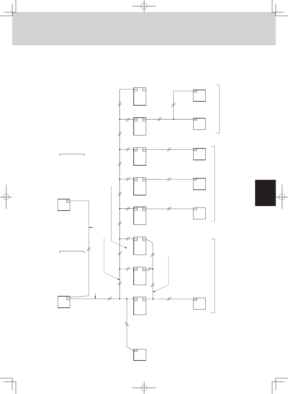
7. System examples
The following diagrams show the system examples and the correct setting
of the switches on the PCB.
ro
od
nI
ti
nu
gni
ri
wl
ort
no
cti
nu-
ret
nI
gni
ri
wl
ort
no
cti
nu-
ro
odt
uo-
ret
nI
gni
ri
wl
ort
no
cti
nu-
ret
nI
lor
tn
oc
lar
tn
ec
rof
gni
ri
w
noi
tc
en
no
C
)ni
a
M(
ti
nu
ro
odt
u
O
et
ats
de
ppi
hs-
yr
otc
aF
1:
FF
O/
FF
O: 1:
FF
O/
FF
O:
FF
O/
FF
O/
N
O:
gni
ri
w
noi
tc
en
no
C
lor
tn
oc
pu
or
gr
of
lor
tn
oc
pu
or
G
et
o
me
R
rell
ort
no
c
et
o
me
R
rell
ort
no
c
et
o
me
R
rell
ort
no
c
et
o
me
R
rell
ort
no
c
lor
tn
oc
dr
ad
nat
S
et
o
me
R
rell
ort
no
c
)ni
a
M(
et
o
me
R
ss
el-r
ell
ort
no
c
met
sy
s
et
o
me
R
rell
ort
no
c
)b
u
S(
lor
tn
oc
et
o
mer
el
pitl
u
M
met
sy
S
rell
ort
no
c
ro
od
nI
ti
nu
ro
od
nI
ti
nu
ro
od
nI
ti
nu
ro
od
nI
ti
nu
ro
od
nI
ti
nu
ro
od
nI
ti
nu
ro
od
nI
ti
nu
Indoor unit address : (No need setting)
1-
1
2-
1
3-
1
4-
1
5-
1
6-
1
7-
1
8-
1
20
0
S
30
0
S
40
0
S
50
0
S
60
0
S
FF
O/
FF
O/
N
O:
FF
O/
FF
O/
FF
O:
70
0
S
01
0
S
)b
u
S(
ti
nu
ro
odt
u
O
et
ats
de
ppi
hs-
yr
otc
aF
1:
FF
O/
FF
O: 1:
FF
O/
FF
O:
FF
O/
FF
O/
N
O:
20
0
S
30
0
S
40
0
S
50
0
S
60
0
S
FF
O/
N
O/
FF
O:
FF
O/
FF
O/
FF
O:
70
0
S
01
0
S
(1) For a system without link
MiniECO-i.indb 61
2007/06/20 16:29:13