System controller (sha-kc64ug), Caution – Sanyo CHX06052 User Manual
Page 66
2-48
Remote Control Functions
4. System Controller (SHA-KC64UG)
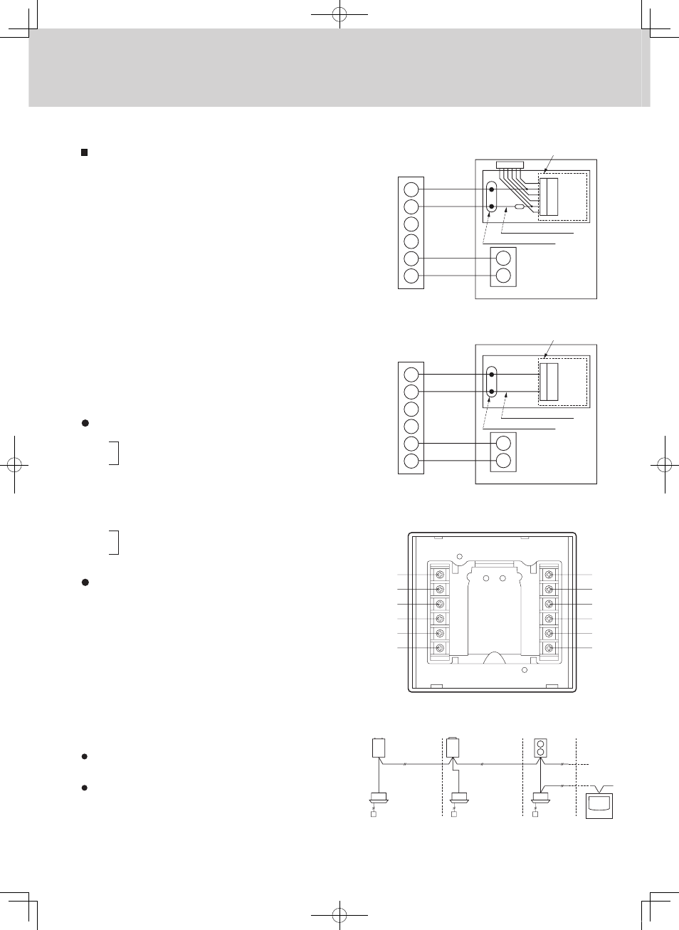
Electrical Wiring
How to connect electrical wiring
For New Model (
**
52 Series)
(1) Connect B1, B2 to indoor PCB T10 connector using
the accessory 6P connector. (with fuse) (*No polarity)
Total wire length is less than 985 ft. and size is
AWG#18.
(2) Connect B5, B6 to indoor unit 2P terminal base.
(*No polarity). Wire size is AWG#18.
For Old Model (
**
42 Series)
(1) Connect B1, B2 to indoor PCB CRV connector using
the accessory 2P connector. (*No polarity)
Total wire length is less than 985 ft. and size is
AWG#18.
(2) Connect B5, B6 to indoor unit 2P terminal base.
(*No polarity). Wire size is AWG#18.
Basic wiring
Terminals for remote monitoring
Basic wiring diagram of control wiring
A max. of 64 indoor units and 30 outdoor units can
be connected in 1 system.
Up to 10 system controllers can be connected in
1 system.
B1
Indoor unit PCB
T10
(YEL)
2P terminal base
Indoor unit
System controller
Accessory connector
Wire joint connection
B2
B3
B4
B5
B6
U1
U2
B1
Indoor unit PCB
CRV
(WHT)
2P terminal base
Indoor unit
System controller
Accessory connector
Wire joint connection
B2
B3
B4
B5
B6
U1
U2
A1
A2
A3
A4
A5
A6
B6
B5
B4
B3
B2
B1
Inter-unit
control wiring
System controller
RC1
1-1
RC2
RC3
2-1
3-1
B1:
B2:
B3:
B4:
B5:
B6:
Power supply: DC12V *No polarity
To CRV connector (CN91)
or T10 connector on indoor PCB
Inter-unit control wiring. (Low voltage)
To indoor unit 2P terminal base (U1, U2)
*No polarity
Auxiliary of inter-unit control wiring
Not be used
A1:
A2:
A3:
Common input for turning air conditioners on or off.
A4:
A5:
A6:
ON operation state indicator output.
Alarm indicator output.
Common indicator output.
Input for turning off air conditioners concurrently.
Input for turning on air conditioners concurrently.
Basic wiring diagram
Ensure that wiring connections are correct. (Incorrect wiring will
damage the equipment.)
1. Lines consisting of dots and dashes (
) indicate inter-unit control
wirings.
2. In. means indoor unit.
3. Up to two system controllers may be connected to one control line system.
CAUTION
1 2
1 2
1 2
1 2
1 2
2
1 2
1
2
1 2
1
In.-1
In.-2
In.-3
In.-4
In.-n
C1
C2
C3
C4
L1
L2
C1
C2
C3
C4
L1
L2
2
1 2
1
1 2
2
1
2
1
Outdoor
unit-1
Outdoor
unit-2
Outdoor
unit-3
Outdoor
unit-m
Ground
Ground
Power supply
(
60 Hz, 208/230 V)
Ground for control wiring
System
controller
System
controller
Power supply
(
60 Hz, 208/230 V)
Ground for control wiring
Remote
controller
Remote
controller
Remote
controller
m : 30
Remote
controller
n : 64
1 2
1 2
1 2
1 2
NOTE
MiniECO-i.indb 48
2007/06/20 16:29:00