Lonworks interface product manual (sha-ln16uab), Assigning central control addresses, Lonworks interface test run – Sanyo CHX06052 User Manual
Page 146: Setting central control addresses, Remote control functions
2-128
Remote Control Functions
7. LonWorks Interface product Manual (SHA-LN16UAB)
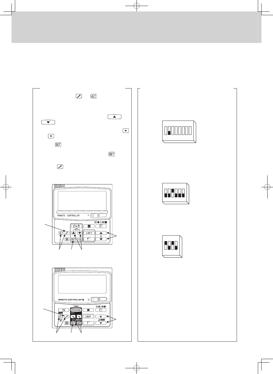
3. Assigning Central Control Addresses
(1) Turn the po wer switch (S001) on the Lon W orks Interface
power board to OFF.
(2) Turn the setting switch (S 006-2) to OFF (so th at central
c ontrol a ddre sses a r e se t with the DIP switc he s).
(3) Set th e first central contro l a ddre ss with the a ddre ss switc h
(S005). When assigning serial n umbers, a consecutive series
of numbers is as signed for th e central contro l a d dre sse s.
circuit board ass igns cent ral control addresses “5,”
“ 6 ,” “ 7 ,” and “ 8 ”.
(4) Make th e en able/d isable se tti ngs with the ind oor unit e n abl i n g
switches (S004).
enabl e onl y “ 5 ” and “ 7 ”.
(5) Turn the po wer switch (S001) on the Lon W orks Interface
power board to ON.
v Before assigning centr al control addresses for th e
LonWorks Interface, use th e r e m o te contro lle r to m a k e
central control address settings f or A/C units.
v Follow on ly th e steps fo r "Assigning C entral Con trol
Addresses" wh en a s ystem controller or other cen tral
controller is alread y provid ed.
[Assigning Central Control Addresses]
OFF
1 2 3 4 5 6 7
OFF
1 2 3 4 5 6
OFF
1 2 3 4
“ 5 ” is s e t as the centr al con t rol
address for indo or unit group 0 ,
a nd “7” i s se t a s t h e ce nt ral
control address for indoor unit
group 2.
S006
S005
S004
(1) Press and ho ld both th e
and
buttons for 4 s econds
or longer .
Check that the " S ETTING" displ a y on the rem o te contro ller is
flashing.
(2) Set the "0 3" item code by pressing th e
an d
temperature setting buttons.
(3) Set th e desired cen tral control address b y pressing the
and
tim er bu tt ons.
(4) Press the
button, and check that the "S ETTI NG" displa y
stops flashing and displays instead.
(The se tting da ta canno t b e chan ged unl ess the
button is
pressed.)
(5) Press the
button, and check th at the d i splay on the
rem o te con t roll e r has b een cl eare d .
RCS-SH80UG
RCS-TM80BG
[Setting Central Control Addresses]
(2)
(4)
(5)
(3)
(1)
(2)
(4)
(5)
(3)
(1)
4. LonWorks Interface Test Run
Before per f or ming a test run of the LonWork s Interface, p e rf orm
test runs of the A/C units and assign centr al control addr esses for
A/C units.
[LonWorks Inter f ace Test Run Pr ocedure]
(1) Press and hold touch-switch S001 on the main circu it board f o r 5
seconds or long er.
Test run m ode is enab led for the m a in cir c u it board tha t is
current l y being controll ed. LD 001 illum i nat e s, and LD002 –
LD008 turn of f.
(2) Press touch-switch S002. The d ata LEDs app ear as shown in the
tables below.
In addition, th e assigned indoor unit groups start and stop as
shown in the tab les below.
(3) Be sure to re set th e power af ter the LonW ork s Interf ac e test r un
is com p let e d.
1
2
Data
3
4
5
6
7
8
1
2
Data
3
4
5
6
7
8
Indoor u n it Gr
0
1
2
3
Sta r t/s to p
Stop
Stop
Stop
Stop
STEP 1
S002 PU S H
1
2
Data
3
4
5
6
7
8
Indoor u n it Gr
0
1
2
3
Sta r t/s to p
Start
Stop
Stop
Stop
STEP 2
1
2
Data
3
4
5
6
7
8
Indoor u n it Gr
0
1
2
3
Sta r t/s to p
Start
Start
Stop
Stop
STEP 3
1
2
Data
3
4
5
6
7
8
Indoor u n it Gr
0
1
2
3
Sta r t/s to p
Start
Start
Start
Stop
STEP 4
S002 PU S H
S002 PU S H
S002 PU S H
S002 PU S H
S002 PU S H
1
2
Data
3
4
5
6
7
8
Indoor u n it Gr
0
1
2
3
Sta r t/s to p
Start
Start
Start
Start
STEP 5
1
2
Data
3
4
5
6
7
8
Indoor u n it Gr
0
1
2
3
Sta r t/s to p
STEP 1
LD
COM
COM
COM
COM
COM
COM
COM
Stop
Stop
Stop
Stop
MiniECO-i.indb 128
2007/06/20 16:30:56