Installing, Wiring, Communication adaptor (sha-ka128aab) – Sanyo CHX06052 User Manual
Page 132: Arrangement of the terminal board and switches, Basic wiring diagram, Wiring procedure, Remote control functions, 1) connecting the power supply, 2) connecting the communication line, Example using an intelligent controller )
2-114
Remote Control Functions
6. Communication Adaptor (SHA-KA128AAB)
S6
S9
S8
S7
D1
D2
UP DOWN SET
HOME
2
3
N
C
A
B
S1
FG AC100~240V
CN1
3
1
CN2
10
0
19
9
D
R
A
O
B
R
E
T
P
A
D
A
AC100V~240V
N
ON
OFF
POWER
ADAPT(RS485) DO-COMMON
DI-COMMON
DO 1 DO 2
+
–
DI 1
DI 2
DI 3
L
10
11
12
13
14
15
16
17
18
19
LINK1
U1
U2
P1
P2
P3
0
1
2
3
4
5
6
7
8
9
(LINK1
–U2)
LINK2
P-COMMON
U1
U2 (LINK2
–U2)
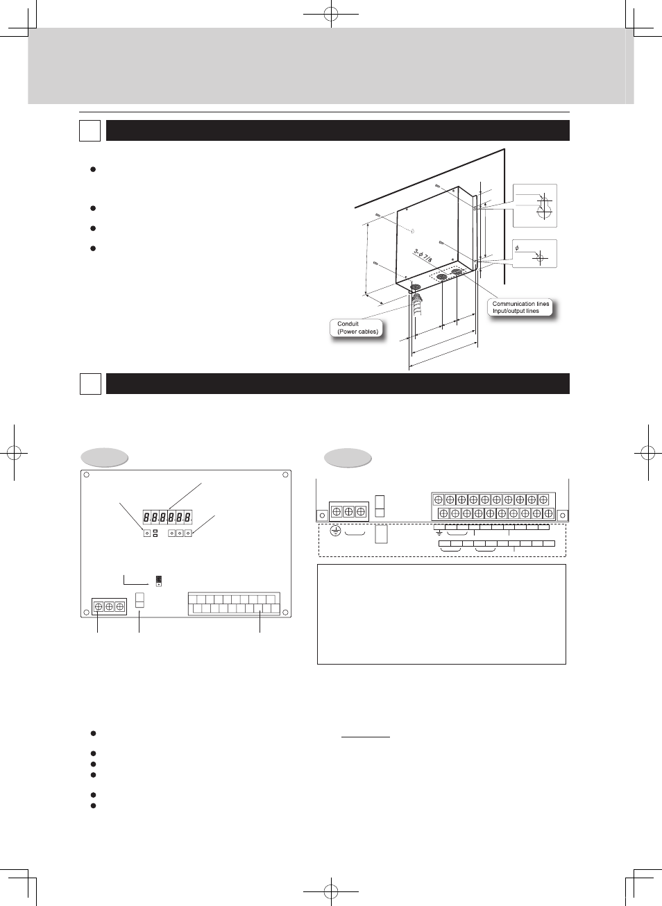
Installing
Note
Do not run the indoor/outdoor communication lines, input/
output lines, and power cables through the same conduit, or
twist those cables together, or place the cables near one
another. It can cause malfunction.
Install the main unit away from any sources of electrical
noise.
Avoid installing in any locations where the unit may come
into contact with water, or in any extremely humid locations.
Avoid installing in any location that is subject to excessive
vibration or physical impacts.
(1) Obtain the installation screws for the main unit on site.
(2) To connect the power cable, attach a conduit to the hole of
the left side and pass the power cable through it as
illustrated on the right.
(3) Tie up the power cable with a snap band to avoid contact
with the board or the signal lines (communication lines and
input/output lines) inside the main unit.
Wiring
Always shut off the power supply (breaker) before installing or uninstalling the Communication Adaptor.
Remove the two screws at the front of the unit and remove the upper case.
Arrangement of the terminal board and switches
Detailed board
illustration
(1) Connecting the power supply
The unit can use AC power sources between 100 and 240 V.
Connect the power supply to terminals 2 (N) and 3 (L) on the power terminal strip CN1. (Connect the AC neutral end to N.)
Connect the ground line securely.
(2) Connecting the communication line
For the Communication Adaptor control wires, use only two-conductor shielded wire with a cross-section between AWG#20 and AWG#14
(MVVS or CPEVS).
Be sure to ground only one end of the shielding.
The overall length of each line should be 3280 ft. or less.
Do not run the communication line through the same conduit as the power supply, use the same cable as the power supply, or run close to
the power supply line (maintain at least 11-13/16 in. separation).
Do not run the LINK1 and LINK2 signal lines through the same conduit, use the same cable for wiring, or run them close together.
Use different communication and power cables so they can be differentiated visually.
Detailed terminal
assembly illustration
7-segment LED
Home key
Up, down and
set keys
Terminating resistance plug
for the Communication
Adaptor control wire
Power supply
terminal strip
Power switch
Signal terminal strip
(see details at right)
2
1
ADAPT +/- : Communication Adaptor control wire (RS-485)
LINK 1/2:
Indoor/outdoor control wire (HBS)
P1:
Pulse meter inputs (gas flow meter and fuel flow meter) (
*
)
P2 and P3: Pulse meter input (power flow meter) (
*
)
DI1:
All stop input (
*
)
DI2:
All operation input (
*
)
DI3:
Reserved
DO1:
All alarm output (
*
)
DO2:
All operation output (
*
)
(*) Input/output function when connecting to the Intelligent Controller
3-7/64
R3/32
R13/64
13/64
10-5/64
1-1/2
7-3/32
1-13/16
1-1/2
5-11/64
2-17/64
2-11/64
10-5/8
11-27/64
(in.)
G
W
Basic wiring diagram
(Example using an Intelligent Controller )
Wire up the Communication Adaptor control wire and Indoor/outdoor control wire as shown in the
figure below.
Intelligent controller
Wiring procedure
Indoor/outdoor control wire
Connect terminals 0 and 1 (LINK1)
on the Communication Adaptor
signal terminal strip CN2 to the
indoor/outdoor control wire terminals
of the indoor or outdoor unit. There is
no polarity.
If connecting two indoor/outdoor
control wire systems, connect
terminals 3 and 4 (LINK2) on CN2 in
the same manner.
Communication Adaptor control wire
Connect terminals 11 and 12
(ADAPT + and -) on the
Communication Adaptor signal line
terminal strip CN2 with the same
terminals on the other
Communication Adaptor. The
terminals have polarity. Connect so
the positive and negative elements
are correct.
When connecting, be sure to use
crossover wiring, not a branching
configuration.
Precautions for the Communication Adaptor control wire
(Some items are duplicated in other sections.)
Indoor/outdoor control wire
Communication
Adaptor control
wire
Communication
Adaptor
Communication
Adaptor
G: Gas flow meter
W: Power flow meter
(1) The overall length should be 3280 ft. or less.
(2) The communication wire has polarity. Connect so the positive and negative elements are
correct.
(3) Use only shielded wire. Be sure to ground only one end of the shielding.
10
11
12
ADAPT
(RS485)
10
11
12
ADAPT
(RS485)
10
11
12
ADAPT
(RS485)
10
11
12
ADAPT
(RS485)
(4) Be sure to use crossover wiring, not a branching configuration.
*
Connect the Intelligent Controller to the end of the crossover configuration.
(5) Change the terminating resistance plug CN32 to the “B” side (with terminal resistance) on the
board for the Communication Adaptors (2 of them) at both ends of the configuration.
23
N
C
B
0
1
2
3
01
11
21
31
A
S1
CN1
FG AC100~240V
B
A
B
A
Communication
Adaptor 1
Communication
Adaptor 2
Communication
Adaptor 3
Communication
Adaptor 4
Intelligent
Controller
Communication
Adaptor
Intelligent
Controller
Communication
Adaptor
3
Terminating resistance
plug for Communication
Adaptor control wire
Terminating resistance
“off” (factory setting)
Terminating
resistance “on”
(6) Do not hook more than 16 units up
to the Communication Adaptor. The
system you are using (such as an
Intelligent Controller) may have
further restrictions. Consult the
installation manual for your system.
*
The Intelligent Controller has a
maximum restriction of seven
units.
(7) Make sure that high voltage (ex. 200
V) AC lines are not connected to the
Communication Adaptor control wire
or the indoor/outdoor control wire
terminals.
*
If high voltage (ex. 200 V) AC is
accidentally applied to the indoor/
outdoor control wire terminals, a
fuse will blow to protect the
controller board. If this happens,
disconnect the 200 V AC line, and
connect the U2 terminal wire of
the indoor/outdoor control wire to
the spare terminal. (Do not
change the U1 terminal wire.)
Spare terminals are located right
next to U2.
Change terminal number 1 LINK1-
U2
m
to terminal number 2 (LINK1-
U2)
Change terminal number 4 LINK2-
U2
m
to terminal number 5 (LINK2-
U2)
Indoor/outdoor control wire
MiniECO-i.indb 114
2007/06/20 16:30:20