Auto address setting, Test run – Sanyo CHX06052 User Manual
Page 11
1-7
Test Run
1
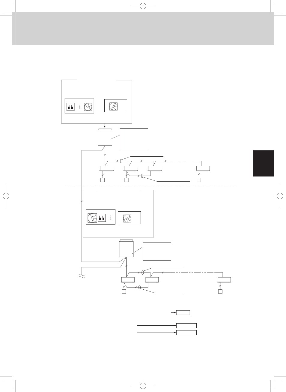
3. Auto Address Setting
1-1
1-2
2-1
2-2
2-7
1-3
1-6
2
7
7
ON
1
2
ON
OFF
Automatic address setting in Heating mode
Automatic address setting in Cooling mode
*
When multiple outdoor units exist, remove the socket that
is used to short-circuit the terminal plug (CN33) from all
outdoor unit PCBs except for 1.
Alternatively, move the sockets to the “OPEN” side.
Leave the socket
that is used to
short-circuit the
terminal plug.
(CN33)
To other system
link wiring
Case 2
Case 1
Case 3
Make settings as appropriate for the cases listed below.
(Refer to the instructions on the following pages.)
Leave the socket
that is used to open
circuit the terminal
plug (CN33).
6
(S004)
1
ON
1
2
ON
OFF
(S003)
(S002)
No. 1 unit settings
Unit
No. 1
Outdoor unit
system 1
Unit
No. 1
Outdoor unit
Indoor unit
Remote
controller
Indoor unit
Remote
controller
Inter-unit control wiring
Inter-unit control wiring
Remote controller
communication wiring
Remote controller
cross-over wiring
(S004)
(S003)
(S002)
No. 2 unit settings
System address
(system 1 setting)
System address
(system 2 setting)
No. of indoor units
(6 units setting)
system 2
No. of indoor units
(7 units setting)
•
If link wiring is used
•
If link wiring is used
•
Indoor and outdoor unit power can be turned ON for each system separately.
•
Indoor and outdoor unit power cannot be turned ON for each system separately.
Basic wiring diagram: Example (2)
MiniECO-i.indb 7
2007/06/20 16:27:57