System controller (sha-kc64ug) – Sanyo CHX06052 User Manual
Page 64
2-46
Remote Control Functions
4. System Controller (SHA-KC64UG)
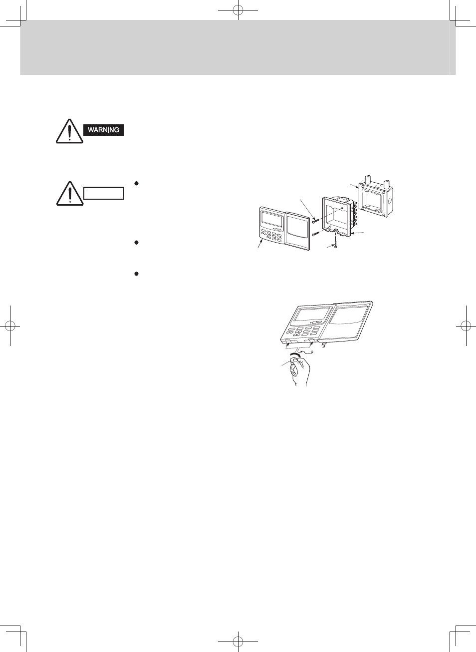
System
controller
Switch box
(with cover)
M4 × 30 mm
Screws (2)
Back case
Cross flat head screw
Gap
Coin
Gap
Do not supply power to the
unit or try to operate it until
the tubing and wiring to the
outdoor unit are completed.
Do not twist the control
wiring with the power
wiring or run it in the
same metal conduit,
because this may cause
malfunction.
Install the system controller
away from sources
of electrical noise.
Install a noise filter or
take other appropriate
action if electrical noise
affects the power supply
circuit of the unit.
(1)
Remove the cross flat head screw on the bottom of the
back case. When you open up the decorative
cover, you will see two gaps under the system
controller. Insert a coin into these gaps and
remove the back case as shown at the right.
(2)
Connect the wires to terminal base of the system
controller (See Electrical Wiring).
(3)
Attach the back case with the 2 M4 screws
provided.
(4)
To finish, fit the back tabs of the back case into
the system controller and mount it using the cross
flat head screw.
CAUTION
N
Installation procedure
N
Layout of electrical terminals
How to connect electrical wiring
1) Basic wiring
2) Terminals for remote monitoring
L1:
Power supply (
60 Hz, 208/230 V)
L2:
C1:
Inter-unit control wiring. (Low voltage)
C2:
C3:
Auxiliary
C4:
Ground for inter-unit control wiring
A1:
Input for turning on air conditioners concurrently.
A2:
Input for turning off air conditioners concurrently.
A3:
Common input for turning air conditioners on or off.
B1:
On operation state indicator output.
B2:
Alarm indicator output.
B3:
Common indicator output.
L1
L2
B3 B2 B1 A3 A2 A1
C1
C2
C3
C4
CN02
Clamp for electrical wiring
Connector (CN02) for
weekly timer or schedule
timer (optional)
P.C. board
Ground for
power wiring
1. HOW TO INSTALL THE SYSTEM CONTROLLER (OpTIONAL pART)
MiniECO-i.indb 46
2007/06/20 16:28:58