Connecting to external equipment, Outer dimensions, Specifications – Sanyo CHX06052 User Manual
Page 137: Communication adaptor (sha-ka128aab), Remote control functions
2-119
Remote Control Functions
2
6. Communication Adaptor (SHA-KA128AAB)
[1] Adaptor number setting
xx = 00 to 15: adaptor number
Sets the Communication Adaptor number.
Set 1 to 7 for the Intelligent Controller, making sure the same number is not used twice.
When actually communicating from a master system, the link system address LINK1 is 2n and
LINK2 is 2n + 1, where n is the Communication Adaptor number.
Thus, when the adaptor number is 2, the LINK1 address is 4 and the LINK2 address is 5.
[7] Local Adaptor connection settings
x = 0: LINK 1 on, LINK2 on
x = 1: LINK 1 off, LINK2 on
x = 2: LINK 1 on, LINK2 off
x = 3: LINK 1 off, LINK2 off
Set whether there is a Local Adaptor (for turning off and on) for each LINK system. If the setting
is “off”, startup will be faster as no Local Adaptor detection is run.
Table 1 Communication Adaptor setting items
Display
[2] Indoor/outdoor control wire connection settings
x = 0: LINK1 on, LINK2 on
x = 1: LINK1 on, LINK2 off
x = 2: LINK1 off, LINK2 on
x = 3: LINK1 off, LINK2 off
Set so any LINK (indoor/outdoor control wire) connected to the air conditioner is “on”, and any LINK
not connected is “off”.
* For solo installation (pulse meter dedicated), use x = 3: LINK1 and 2 both set to off.
(1.Ano.xx)
[3] Base unit settings
Always use 0 (the initial value).
(2.AdYu.x)
(3.Cont.x)
(4.CAn1.x)
(5.CAn2.x)
(6.PUL.xx)
(7.LoCA.x)
(8.SCAn.x)
[4] Settings for the number of Communication Adaptor units in one link, part 1
x = 0 to 7
x = 0: First Communication Adaptor in the LINK1 link
x = 1: Second Communication Adaptor in the LINK1 link
x = 7: Eighth Communication Adaptor in the LINK1 link
[5] Settings for the number of Communication Adaptor units in one link, part 2
x = 0 to 7
x = 0: First Communication Adaptor in the LINK2 link
x = 1: Second Communication Adaptor in the LINK2 link
x = 7: Eighth Communication Adaptor in the LINK2 link
Set the Communication Adaptor unit number for each LINK system when connecting multiple
Communication Adaptors to one indoor/outdoor control wire.
[6] Minimum pulse input detection time setting
x = 03: 30 msec
x = 10: 100 msec
If connecting a pulse meter with a pulse width between 30 and 100 msec, set to 30 msec.
[8] Initial communication setting
Always use 0 (the initial value).
Setting item ( grayed in areas indicate factory setting)
DOWN
UP
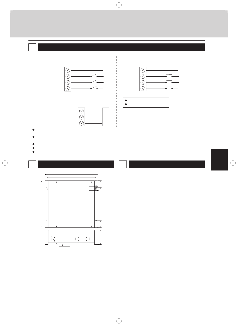
Connecting to external equipment
5
(1) External all input (No-voltage a-contact
static)
DI–COMMON
DI 1
DI 2
DI 3
(2) External all output (No-voltage a-contact
static)
DO–COMMON
DO 1
DO 2
(3) Pulse meter input (No-voltage a-contact
pulse)
P–COMMON
P1
P2
P3
Minimum pulse width: 100 msec
Minimum pulse interval: 1 sec
(
*
) Input/output function when connecting to the Intelligent
Controller
Gas flow meter (
*
)
(fuel flow meter)
Keep the signal input line lengths to 66 ft. or less. For distances greater than this, install a standalone Communication Adaptor or use
a relay.
For use in areas that may be susceptible to electrical noise, use a two-conductor shielded cable (with one line grounded), with a cross-
section at least AWG#20.
Do not apply external voltages to the input terminals.
About 10 mA of 5 V DC voltage is applied to the contact point for input terminal detection.
The output terminal allowable contact voltage and current are 30 V DC and 0.5 A.
All stop input (
*
)
All operation input (
*
)
(Reserved)
(Common output)
(
*
) All alarm output
(
*
) All operation output
Equipment
t
u
p
ni
l
ati
gi
D
Power flow meter 1 (
*
)
Power flow meter 2 (
*
)
Outer dimensions
6
Specifications
Rated voltage ........................................ Single phase 100 to 240V
Rated frequency ................................... 50/60 Hz
Power consumption .............................. 5.6 W max
Operating temperature ......................... 14–122ºF (–10 to +50ºC)
Operating humidity ............................... 20 to 80% (no condensation)
Weight ................................................... 3.97lb (1.8 kg)
7
Equipment
1
0
-5
/6
4
11-27/64
3
-7
/6
4
1
-1
/2
3- 7/8
(in.)
1
-1
/2
13/64
7
-3
/3
2
10-5/8
25/64
MiniECO-i.indb 119
2007/06/20 16:30:33