Power, Power -14, Figure 1-10 – Juniper Networks ERX-1410 User Manual
Page 34
CHAPTER 1
ERX System Overview
1-14
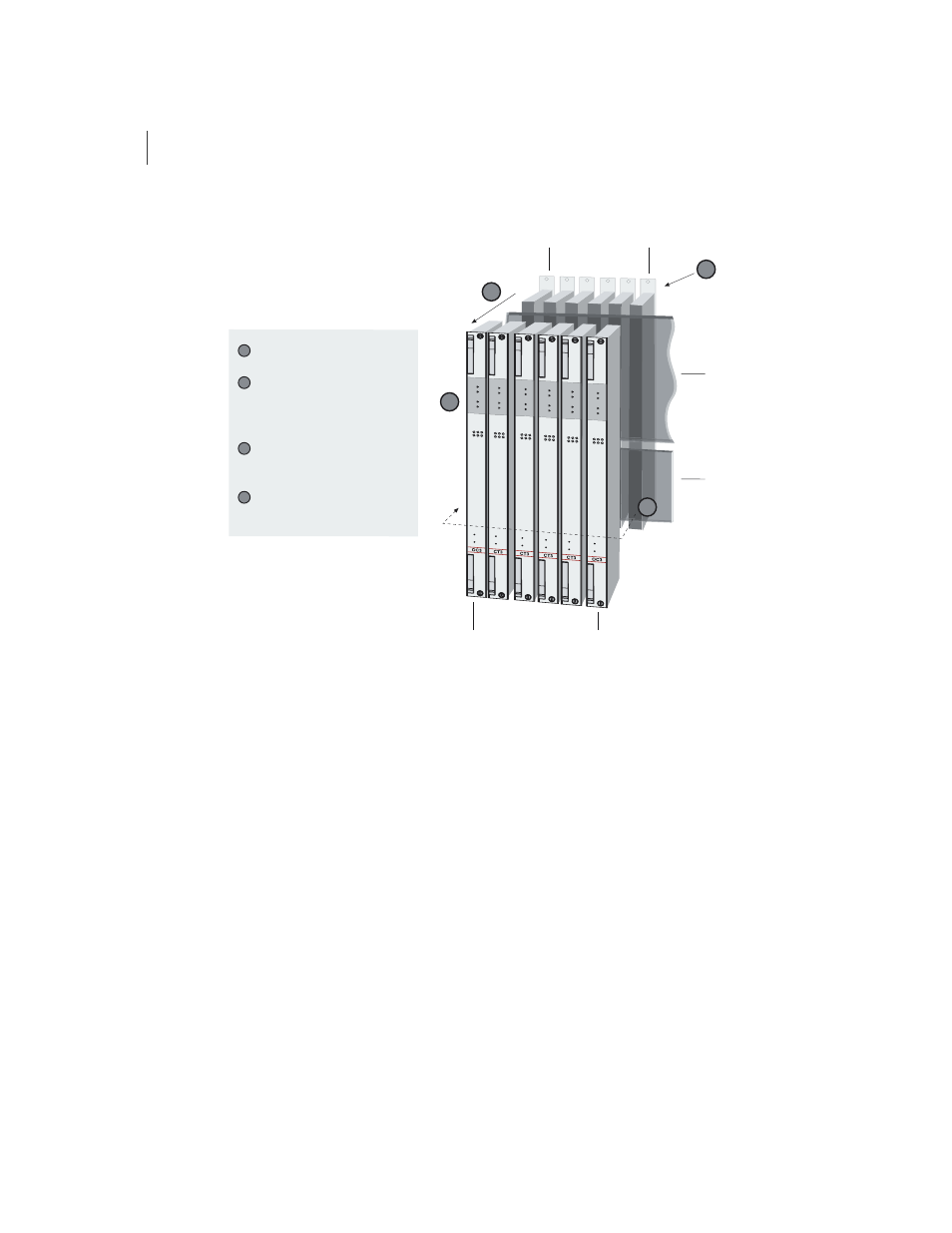
Figure 1-10 Data flow when a spare line module is active
For information about installing modules for line module redundancy, see
Chapter 3, Installing ERX Modules
. For information about configuring
and managing SRP module redundancy, see
ERX System Basics
Configuration Guide, Chapter 5, Managing Line Modules and SRP
Modules
, for more information.
Power
The system provides a power architecture that distributes redundant
–48 VDC feeds through the system to each line module, SRP module,
and fan module where DC-to-DC converters provide local conversion to
the required secondary voltages. The system design prevents a failure of
any one of the power components from causing any other component in
the system to fail.
1
2
4
3
Midplane
Redundancy
midplane
Primary
line module
Spare
line module
Redundancy
I/O module
Primary
I/O module
A packet arrives at the primary
I/O module.
The packet passes along the
redundancy midplane from the
primary I/O module to the
redundancy I/O module.
The packet passes from the
redundancy I/O module to the
spare line module.
The spare line module
processes the packet.
1
2
3
4