Intel SR9000MK4U User Manual
Page 42
20
Intel
®
Server System SR9000MK4U Product Guide
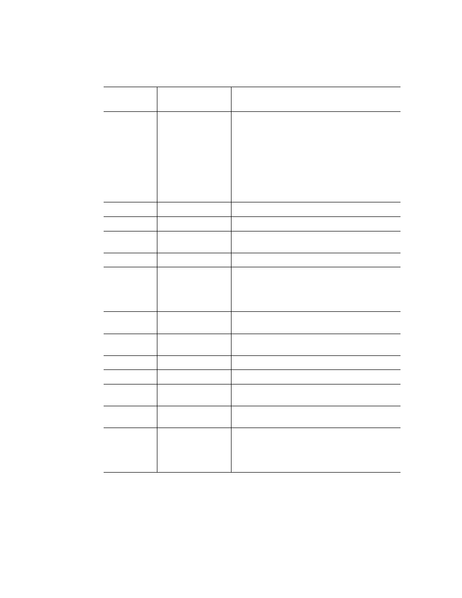
P9
LSI Logic* SAS1068
PCI-X* to 3 Gb/s 8-port SAS controller. Four of the
eight ports are used.
•
1.5 and 3 Gb/s SAS and SATA data transfer
rates per port, full duplex
•
64-bit, 133 MHz PCI-X host interface
•
Integrated RAID support
–
Fusion-MPT* architecture
–
Integrated Striping* technology (RAID0)
–
Integrated Mirroring* technology (RAID1)
P10
H8S/2166
Baseboard management controller (BMC)
P11
SIO
Super I/O
P12
FPGA
Management interface and shared memory extension
bridge
P13
Battery
CMOS backup
P14
ID SW
This is a button combined with an LED. It can be used
to identify a particular system and is useful in locating
a particular system among many. The first time the
button is pressed, the LED turns on. If the button is
pressed again, the LED will blink and then turn off.
P15-P20
PCI-X* / PCI-
Express* slot
Attention
Switch
Switch used for hot
swapping PCI cards.
P21
7SEG LED
Indicates POST code
P22-P27
PCI-X/e slot
Power LED
LED to indicate an
active PCI slot status
P28-P33
PCI-X / PCI-Express*
slot
Attention LED
LED to indicate an
error other PCI card
slot condition. See
.
Table 7. Main Board Components
Board
Location
Component
Description