Chassis rear, Figure 7. chassis rear view – Intel SR9000MK4U User Manual
Page 31
Intel
®
Server System SR9000MK4U Product Guide
9
Chassis Rear
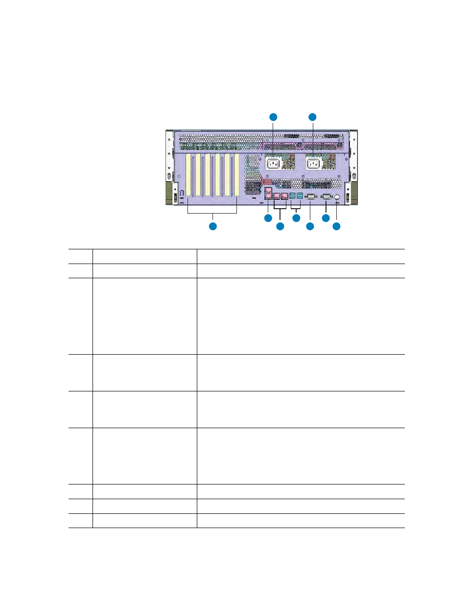
Figure 7 shows the features found on the rear panel.
Figure 7. Chassis Rear View
AF001087
A
B
C
D
E
F
G
H
I
A
AC input power connectors
B
AC input power connectors
C
PCI Slots
All slots support hot-plug PCI add-in cards. From left to right:
–
Slot 6: 133 MHz, 64-bit PCI-X*, full length
–
Slot 5: PCI-Express* x 16, half length
–
Slot 4: PCI-Express x 8, half length
–
Slot 3: 133 MHz, 64-bit PCI-X, half length
–
Slot 2: PCI-Express x 16, half length
–
Slot 1: PCI-Express x 8, half length
D
Dual Gb Ethernet ports
RJ45 connectors. See Table 5 for LED information.
–
GbE1: top
–
GbE0: bottom
E
100 Mb Ethernet ports
RJ45 connectors. See Table 5 for LED information.
–
Ether0: left. Management LAN port
–
Ether1: right. KVM LAN port
F
Four USB ports
4-pin connectors:
–
Top left: RUSB3
–
Bottom left: RUSB2
–
Top right: RUSB1
–
Bottom right: RUSB0
G
Video port
Standard VGA compatible, 15-pin connector
H
Serial port
9-pin RS-232 connector
I
Identification Button
Toggles chassis ID LED on/off.