Front panel, Figure 3. front panel controls and indicators – Intel SR9000MK4U User Manual
Page 27
Intel
®
Server System SR9000MK4U Product Guide
5
Front Panel
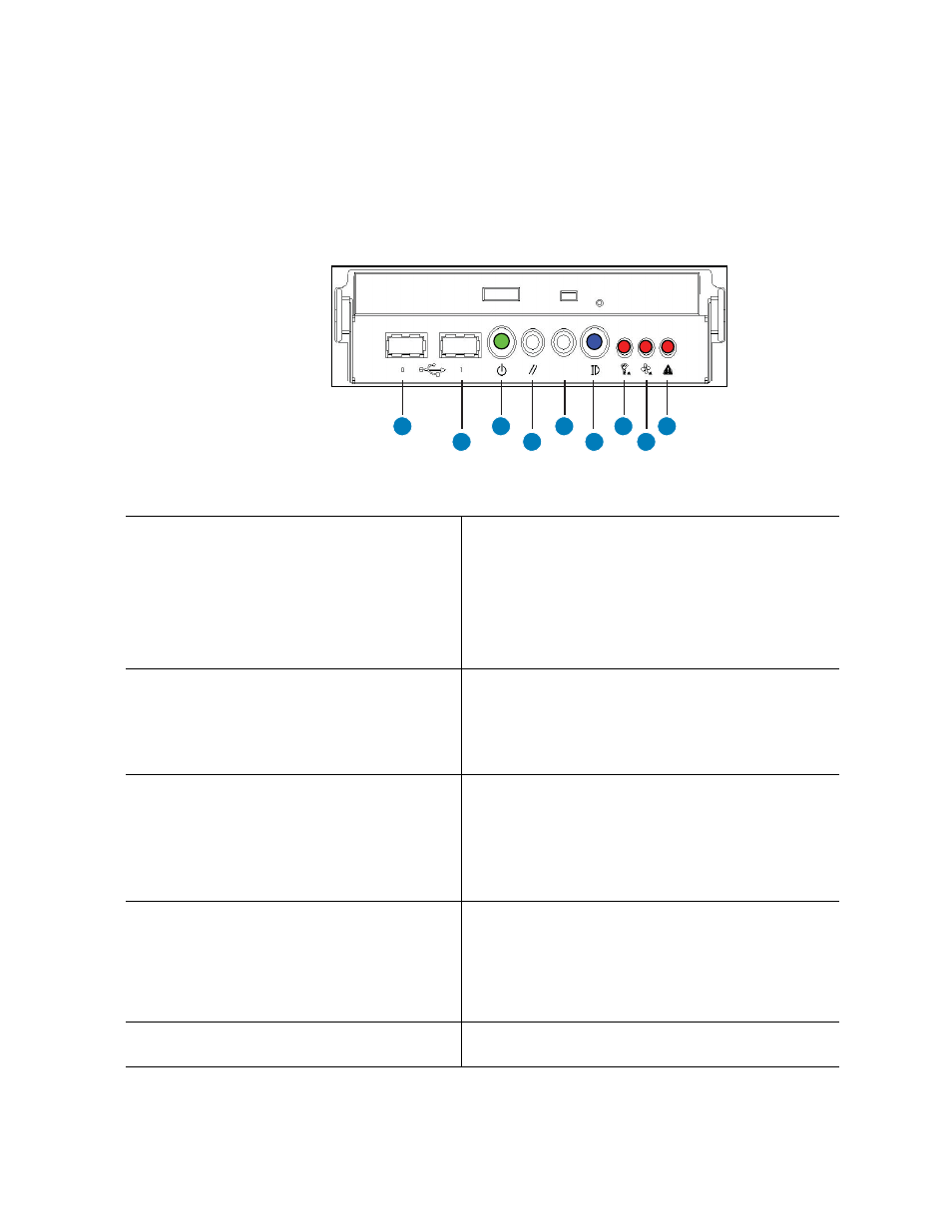
The front panel is located below the slimline optical drive on the left-side of the chassis
front. The front panel provides buttons and status indicator LEDs. Figure 3 shows the
control buttons and status indicators on the front panel.
Figure 3. Front Panel Controls and Indicators
AF001083
E
D
C
B
A
F
G
H
I
A.
USB Port 0, USB 1.1. The port is shut down in
case of an over-current. To recover, power
down server and then power it back on.
F.
Identification button and blue ID LED. Button toggles
state of LED between on and off.
–
Blue on: Identifies server.
–
Blue blink: CMOS being cleared or FWH recovery
in process. For instructions on how to clear the
CMOS, see
“Clearing the CMOS” on page 140
–
Off: System not identified, CMOS not being
cleared, FWH recovery not in process.
B.
USB Port 1, USB 1.1. The port is shut down in
case of an over-current. To recover, power
down server and then power it back on.
G. Power fault LED:
–
Orange on: Critical, non-recoverable power fault
detected.
–
Orange blink: Non-critical power fault detected.
–
Off: No power fault detected.
C. Power button and power LED.
–
Green on: ACPI S0 state.
–
Green blink: System is powering down.
–
LED off: ACPI S5 state.
For information about power the system on and off,
see
“Powering the System On and Off” on page x
.
H. Cooling fault LED:
–
Orange on: Critical non-recoverable cooling fault
detected.
–
Orange blink: Non-critical cooling fault detected.
–
Off: No cooling fault detected by the BMC.
D. Reset button: Resets the system.
I.
General fault LED:
–
Orange on: Critical, non-recoverable fault other
than power or cooling fault detected.
–
Orange blink: Non-critical fault other than power or
cooling fault detected.
–
Off: No general fault detected.
E.
System diagnostic interrupt (SDINT) button:
Asserts INIT to system.