Universal serial bus ports, Usb cables and hubs – IBM 220 User Manual
Page 74
64
IBM® xSeries 220 User’s Reference
Configuration/Setup Utility program to change serial port address assignments to
prevent or resolve address conflicts.
Viewing or changing the serial-port assignments
To view or change the serial-port assignments, do the following:
1. Restart the server and watch the monitor screen.
2. When the message Press F1 for Configuration/Setup appears, press F1.
3. From the main menu, select Devices and I/O Ports; then, press Enter.
4. Select the serial port; then, use the arrow keys to advance through the available
settings.
5. Select Save Settings; then, select Exit Setup to exit from the Configuration/Setup
Utility main menu.
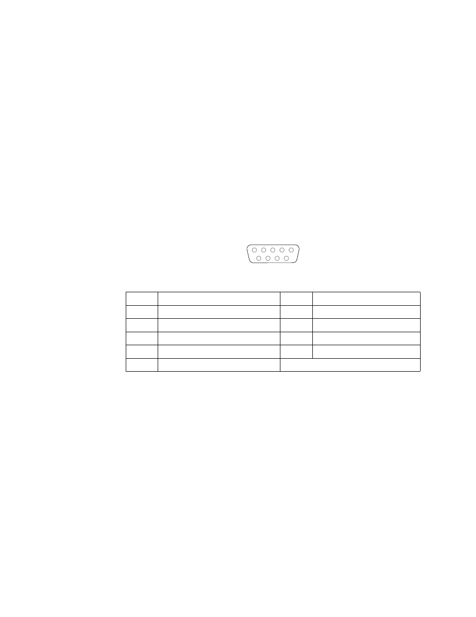
Serial-port connectors
The following table shows the pin-number assignments for the 9-pin, male D-shell
serial-port connectors on the rear of the server. These pin-number assignments
conform to the industry standard.
Universal Serial Bus ports
Your server has two Universal Serial Bus (USB) ports, which configure automatically.
USB is a serial interface standard for telephony and multimedia devices. It uses Plug
and Play technology to determine the type of device that is attached to the connector.
Notes:
1. If you attach a standard (non-USB) keyboard to the keyboard connector, the USB
ports and devices will be disabled during the power-on self-test (POST).
2. If you install a USB keyboard that has a mouse port, the USB keyboard emulates a
mouse, and you will not be able to disable the mouse settings in the
Configuration/Setup Utility program.
USB cables and hubs
You need a 4-pin cable to connect devices to USB 1 or USB 2. If you plan to attach
more than two USB devices, you must use a hub to connect the devices. The hub
provides multiple connectors for attaching additional external USB devices.
Pin
Signal
Pin
Signal
1
Data carrier detect
6
Data set ready
2
Receive data
7
Request to send
3
Transmit data
8
Clear to send
4
Data terminal ready
9
Ring indicator
5
Signal ground
Table 5. Serial-port connectors pin-number assignments
1
5
6
9