2 connecting rocs to servers, 1 connector table – Minicom Advanced Systems SMARTRACK 116 IP User Manual
Page 16
SMARTRACK 116 IP
15
7.1.1 Connector table
Connector
Function
Serial
This port is for future Serial functionality
Flash
To update firmware of the analogue part of the 116 IP Switch
system - OSD, Switch, ROCs.
LAN
Connect to 10/100 Mbit Ethernet. Yellow Led illuminates when
connected to LAN. Green LED illuminates when a remote session
is in progress
Server ports
Connect to servers via ROCs
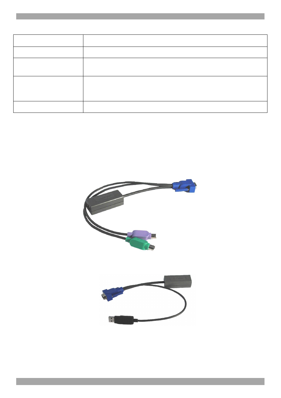
7.2 Connecting ROCs to servers
Each computer/server is directly connected to the SmartRack switch via the
appropriate ROC using CAT5 cable in a star configuration. No external power is
needed at the remote ROCs. The ROCs draw their power from the computer’s
keyboard port (ROC PS/2) or from the USB port (ROC USB). The figures below
illustrate the ROC PS/2 and ROC USB.
To computer’s
keyboard port
To computer’s
mouse port
To computer’s
Video card
Figure 19 ROC PS/2
To computer’s
USB Port
To computer’s
Video Card
Figure 20 ROC USB
7.2.1 Connecting a ROC PS/2
Figure 21 illustrates the ROC PS/2 connections.
You can connect the ROC PS/2 to a powered on computer, but it must be in the
following order: