The smartrack switch system configuration, 1 the 116 switch, User guide – Minicom Advanced Systems SMARTRACK 116 IP User Manual
Page 15: User over ip
USER GUIDE
14
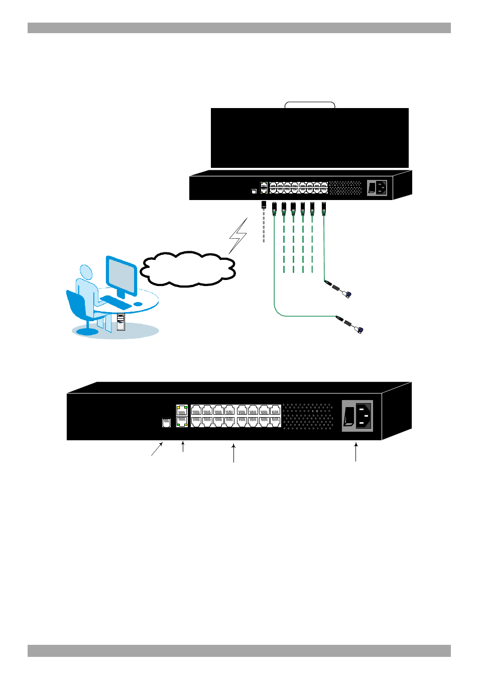
7. The SmartRack Switch system configuration
You connect servers to the 116IP switch via ROCs. Figure 17 illustrate the basic
configuration of the 116IP system.
1
2
3
4
5
6
7
8
10
11
12
13
14
15
16
9
MINICOM
I
0
SMARTRACK 116IP SWITCH
FLASH
LAN
SERIAL
To servers
ROCs
to servers
User over IP
Internet / VPN / LAN
SMARTRACK 116IP SWITCH
CAT5 cables
Up to 30M / 100ft
Figure 17 SmartRack 116IP Switch system configuration
7.1 The 116 switch
Power
connector
Server ports
LAN (Ethernet)
connector
Flash
(download)
connector
1
2
3
4
5
6
7
8
10
11
12
13
14
15
16
9
MINICOM
I
0
SMARTRACK 116IP SWITCH
FLASH
LAN
SERIAL
Figure 18 116IP Switch ports