Threading, Notice – Grizzly G0554 User Manual
Page 41
G0554 Gear-Head Floor Lathe
-39-
4. Drop the large gear set out of mesh and tem-
porarily lock in place by tightening the hex nut
loosened in
Step 3.
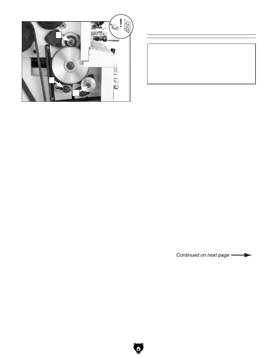
5. Remove the cap screw in Figure 57, Item
B or C, depending on which gear is to be
changed.
Note: To loosen the cap screw, it may be
necessary to wedge a small piece of wood
between the two gears to keep them from
spinning.
6. Install the new gear(s) and tighten in place
with the cap screw removed in
Step 5. DO
NOT overtighten. These cap screws merely
hold the gear in place. Overtightening will
make them harder to remove later.
7. Loosen the hex nut in Figure 57, Item A, and
move the gear set up until the larger gears
mesh with the smaller gears. Tighten the
nut to hold the large gear set in place. Make
sure there is a gap of 0.001"-0.002" between
gears.
Note: Setting the gears too tight will cause
excessive wear and noise. Setting the gears
too loose may cause slippage and possibly
break gear teeth.
8. Close the end cover door and reconnect
power to the machine.
Figure 57. Gear change locations.
Threading
1. Set the compound rest to the appropriate
angle for the given thread you want to cut.
For a Unified National Series thread, this is
29º off vertical to spindle axis.
2. Set the tool tip perpendicular to the workpiece
and center it vertically.
3. Make sure the thread dial is engaged with
the lead screw. If not, use a hex key wrench
to loosen the screw and rotate the thread dial
until the gear engages with the lead screw,
then tighten the screw to hold the dial in
place.
4. Select the RPM you want to use. A slower
RPM will give you more time to react espe-
cially if threading over a short distance or
threading up to a shoulder.
5. Set the feed direction lever for either right or
left-handed threads.
6. Examine the thread charts (inch or metric),
see
Figure 58, and then set the feed rate
selectors to the appropriate settings.
Failure to follow RPM and feed rate guide-
lines in this manual will put undue strain
on moving parts, shorten tool life, and cre-
ate poor workpiece results.
NOTICE
A
B
C