Grizzly G0554 User Manual
Page 37
G0554 Gear-Head Floor Lathe
-35-
�������
�������
������
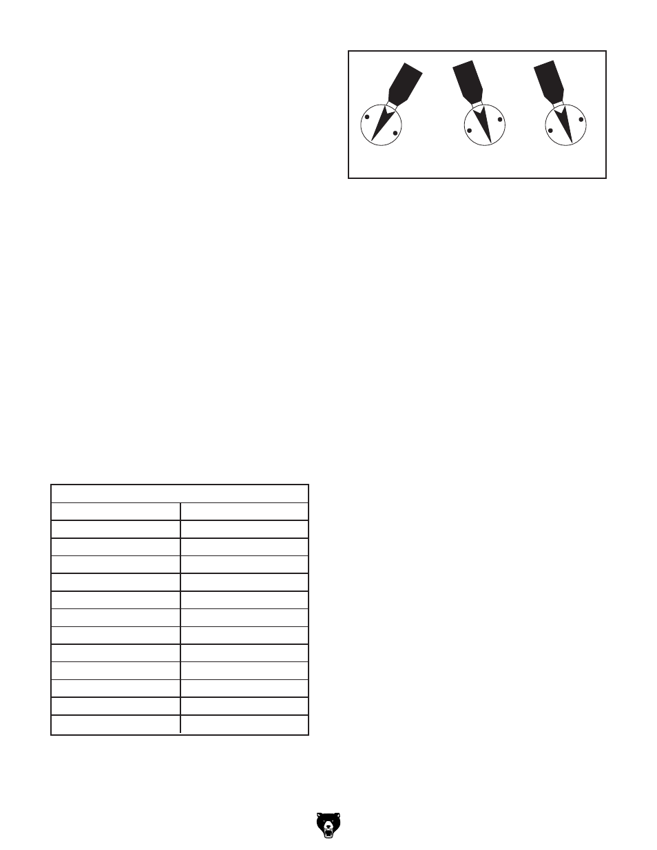
Figure 50. Spindle speed selectors shown set at
1280 RPM.
2. Determine the final diameter, in inches, for
the cut you are about to take.
Note: For this step you will need to aver-
age out the diameters or work with the finish
diameter for your calculations.
3. Use the following formula to determine the
needed RPM for your operation:
(Cutting Speed x 4)/Diameter of cut = RPM
4. With the calculated RPM, examine the spin-
dle speed chart in
Figure 49 or on front of the
headstock, to find the closest match.
Note: In most cases you will need to make a
judgement call on which way to go with the
RPM.
5. Make sure the spindle is completely stopped
before proceeding.
6. Move the spindle speed selectors (Figure
50) to the appropriate RPM setting. Refer to
Figure 49 for available RPM and the selector
combinations.
Note: You may need to rotate the spindle by
hand to get the levers to properly engage.
Figure 49. RPM chart.
SPEEDS
LEVERS
RPM
JLP
1800
GLP
1280
HLP
910
JLM
650
GLM
460
HLM
325
JKP
230
GKP
160
HKP
115
JKM
85
GKM
60
HKM
40