Setting feedrate, Notice, Figure 53. feed rod lock knob – Grizzly G0554 User Manual
Page 39
G0554 Gear-Head Floor Lathe
-37-
Setting Feedrate
1. Turn the spindle OFF and wait until it comes
to a complete stop before making any gear
changes.
2. Move the feed rod lock knob to the open
position (see
Figure 53). This will disengage
the feed rod so gears can be changed.
Figure 55. Feed and Thread Chart in IPR, TPI and metric pitch.
���
���
���
���
���
�
���
����
��
��
��
��
�
���
���
���
���
���
���
���
���
��� ���� ���
���
����
��� ���� ���
���
���
����
���
��� ����
�
�
�
�
�
�
���
���
���
���
��
��
��
��
��
��
��
��
��
��
���
���
��
��
��
�
�
�
�����
�����
�����
�����
�����
�����
�����
����� �����
�����
�����
�����
�����
�����
����� �����
�����
�����
�����
�����
�����
�����
�����
�����
�����
�����
�����
�����
�����
�����
�����
�����
�����
�����
�����
�����
�����
�����
�����
�����
�
�
�
�
�
�
�
�
�
�
�
�
������
�
�
�
��
��
��
�����
�
��
��
��
��
��
��
��
��
��
��
��
��
��
��
��
��
��
���
���
�����
������
������
�
��
�����
�
�
�
��
��
��
�
�
��
�
�
�
��
�
��
����
������
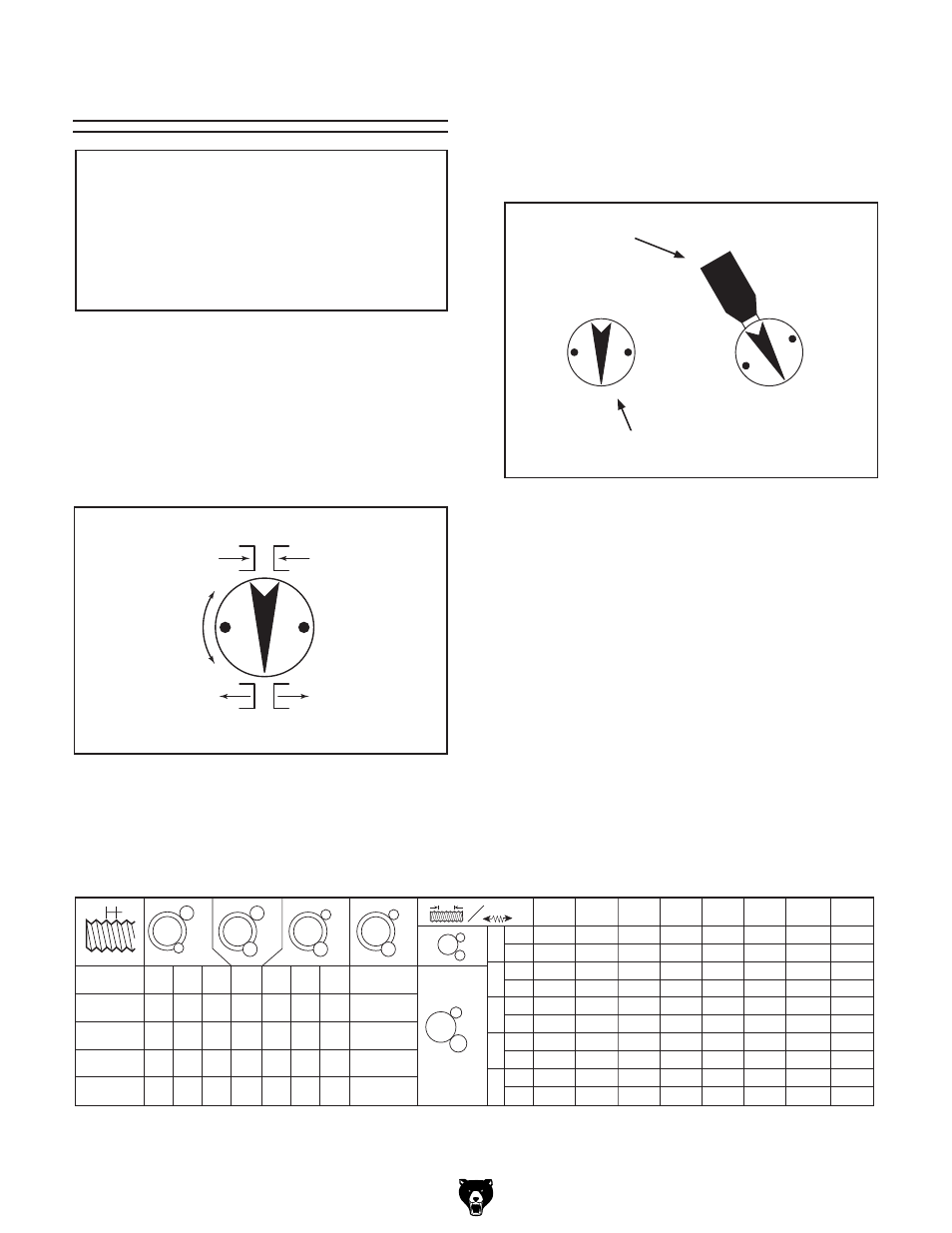
Figure 53. Feed rod lock knob.
NOTICE
Make sure all power feed settings are
disengaged before starting the lathe!
Thoroughly familiarize yourself with all the
controls and their functions before using
power feed!
Figure 54. Feed rod/lead screw selector.
�
������������
�
�
�
�
�
�
�
�
C/D/E/F Feed/Lead Selector
1-8 Feed Rod Selector
For example: To set the lathe to the slowest
feed rate of 0.0011" per inch, locate 0.0011
on the chart. The lever combination on the
chart is B, F and 8. Set the appropriate levers
to these positions.
Note: You may need to rotate the chuck by
hand or move the longitudinal handwheel to
get selectors and gears to engage.
5. Return the feed rod lock knob to the locked
position to engage the feed rod.
3. Examine the feed/thread chart (Figure 55) to
determine the correct lever combination for
the desired feedrate.
4. Feeds rates are controlled by the combina-
tion of three different switches. The A/B feed/
lead selector in
Figure 54, the 1-8 feed rod
selector, and the C/D/E/F feed/lead selector
combinations in
Figure 54.