Front panel board – Gateway 7250R User Manual
Page 16
Front panel board
9
Front panel board
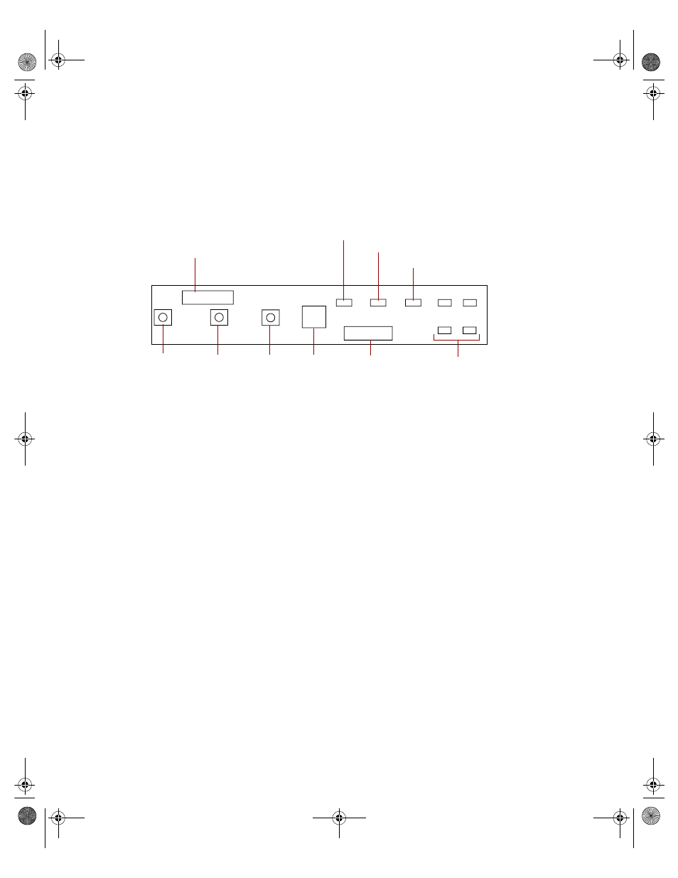
The front panel board supports the LEDs and buttons accessible from the front
panel. The buttons and LEDs on the front panel board are shown and
described below.
Front panel connector connects the controls on the front panel with the
system board.
Power LED glows green whenever the system is turned on. The LED also
flashes when the system is in sleep mode.
Network activity LED lights whenever there is activity on the network.
System fault LED flashes whenever the system logs a failure.
Disk activity LEDs glow green whenever the hard disk is actively reading or
writing data and glow amber if the disk fails.
Backplane connector carries signals from the hot-plug backplane to the
control panel.
NMI switch allows a technician servicing the server to generate a
non-maskable interrupt (NMI) to help debug server errors.
Reset button lets you reset the server if it has become nonresponsive.
Sleep button lets you put the server into sleep mode to reduce power
consumption.
Power button turns the server on and off.
Power LED
Disk activity/fail LEDs
Reset
button
Power
button
Sleep
button
Network activity LED
Backplane
connector
Front panel connector
System fault LED
NMI
switch
ID0
ID1
ID2
ID3
8506162.book Page 9 Wednesday, May 10, 2000 10:21 AM