Input connections – GTO GP-SW050 User Manual
Page 23
20
1
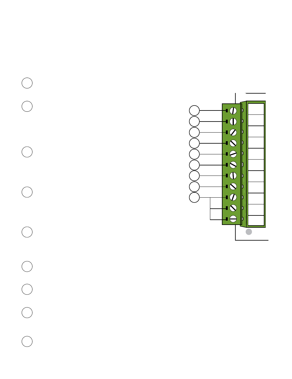
CYCLE:
(Typically for use with doorbell button or hardwired key pad)
• Each activation at this input will cycle the operation as follows:
….→ OPEN → STOP → CLOSE → STOP → OPEN → …
2
SAFETY:
(Typically for use with photo beam device, loop detector
or other non-contact sensors)
• Activation of this input while the gate is closing will cause the gate to
stop and return to the opened position.
• Activation of this input while the gate is opening has no effect (gate
will continue to open).
• Activation of this input while gate is idle will prevent gate from closing.
3
SHADOW:
(Typically for use with loop detector device)
• This input is only monitored when the gate is at the fully open
position. At any other position, activation of this input has no effect on
gate operation.
• Activation of this input while gate at the fully open position will
prevent gate from closing.
4
OPEN EDGE:
(Typically for use with safety edge device)
• Activation of this input while the gate is opening will cause the gate to
stop and reverse direction for approximately 2 seconds.
• Activation of this input while the gate is closing has no effect (gate
will continue to close).
• Activation of this input while gate is idle will prevent gate from opening.
5
CLOSE EDGE:
(Typically for use with safety edge device)
• Activation of this input while the gate is closing will cause the gate to
stop and reverse direction for approximately 2 seconds.
• Activation of this input while the gate is opening has no effect (gate will continue to open).
• Activation of this input while gate is idle will prevent gate from closing.
6
OPEN:
(Typically for use with exit loop or wand)
• Activation of this input will open the gate if it’s not already at the open position
• Activation of this input while at open limit will restart the auto close time (if enabled).
7
CLOSE:
(Typically for use with 3-button control station)
• Activation of this input will close the gate if it is idle AND not already at the closed position.
• Activation of this input while gate is opening will stop the gate.
8
STOP:
(For use with 3-button control station that has ‘NORMALLY CLOSED’ STOP button)
• Activation of this input will stop the gate.
• Jumper ‘W1’ must be cut when using normally closed ‘STOP’ button.
• A normally closed button must be connected to ‘STOP’ and ‘COM’ in order for gate to operate.
9
COM:
Circuit common (reference for all accessory inputs)
• Three (3) terminals to provide extra common connection point.
input connections
1
2
3
4
O
N
LOCK
COM
COM
COM
ALARM
CYCLE
SAFETY
SHADOW
OPEN
CLOSE
STOP
OPEN
EDGE
CLOSE
EDGE
STATUS
STALL FORCE ADJUST
LIMIT ADJUSTMENTS
DUAL
LINK
GTO LOOP DETECTORS
LIMIT SENSORS
DIAG.
PORT
BLDC SPEED CONTROL
EXIT SHADOW SAFETY
AT OPEN
LIMIT
PRISON
MODE
RUNNING
OPTIONS
TEST SWITCHES
CLOSE
STOP
OPEN
GTO Inc. Tallahassee, FL
SX4000 Logic Board Rev. E
MIN
MAX
MIN
MAX
OFF
120
<<< JOG >>>
<<< >>>
SET
LIMIT
CLOSED
LED11
LED10
LED09
+ ACC. PWR.
12VDC
- 300ma
W1
CUT TO USE
3 BUTTON
STATION
AUTO CLOSE
TIMER
MODE 1
MODE 2
OPEN DIR.
SLV OPN
DUAL MODE
LOW BATT
ON
ON
>>>
SIMUL
SLAVE
SECURE
OFF
OFF
<<<
DELAY
MASTER
SAFE
A
C
C.
PO
WER
DU
AL C
ABLE
+12Vdc
COM
DUAL LINK
LINK COM
REL
AY OUTPUT
S
LOCK N.C.
LOCK COM
LOCK N.O.
RUN 1
RUN 2
CLOSED 1
CLOSED 2
CYCLE
SAFETY
OPEN EDGE
CLOSE EDGE
OPEN
CLOSE
STOP
COM
COM
COM
SHADOW
LOOP
1
2
3
4
5
8
9
6
7
NOTE:
• All control inputs are dry-contact, normally open, inputs except for #8. DO NOT apply external voltage
sources to these inputs.
• All inputs are connected with respect to
COMMON
terminal.
• All inputs have a corresponding LED indicator for diagnostic purposes. All input LED indicators, except for the
STOP LED
, will be dimly lit when its corresponding input is inactive and brightly lit when it is activated.