Connecting power to the operator – GTO GP-SW050 User Manual
Page 16
13
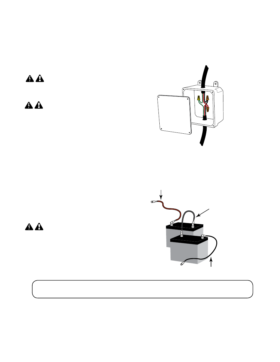
RED
WIRE
to positive (+)
JUMPER WIRE
(Supplied)
RED WIRE
to positive (+)
BLACK WIRE
to negative (–)
JUMPER WIRE
(Supplied)
negative (-) to positive (+)
BLACK
WIRE
to negative (–)
2.
Connect batteries to operator as shown. The red wire connects to the positive terminal
in the control box. The black wire connects to the negative terminal in the control
box. The jumper wire (included) connects both batteries together with the remaining
terminals. Wire the 24V system in series as shown below.
3.
Turn on AC power at this time.
NOTE:
Battery should be a 12 Vdc, U1,
230 Amp Minimum, Lead Acid Battery
(Typical Lawn and Tractor Battery).
NOTE: When first turning operator power switch on, the unit may beep once
every 5 seconds until the new batteries can be fully charged (30-60 minutes charging time).
1. Turn the breaker power switch off before connecting AC power. Have a licensed electrician
run 115 Vac wiring into the Field Wiring Connection Compartment. The 115 Vac line will power
the gate operator system. The circuit must be protected with a 15 A main disconnect breaker
(not provided).
NOTE:
Power and wiring connections MUST be
performed by a licensed electrician in accordance
with NEC (National Electric Code) and local codes.
NEVER
run low voltage (e.g., accessory or receiver)
wires in conduit containing 115 Vac wiring.
connecting Power to the operator