Dip switch settings – GTO GP-SW050 User Manual
Page 22
19
1
2
3
4
O
N
LOCK
ALARM
CYCLE
SAFETY
SHADOW
OPEN
EDGE
STATUS
STALL FORCE ADJUST
DUAL
LINK
GTO LOOP DETECTORS
LIMIT SENSORS
DIAG.
PORT
BLDC SPEED CONTROL
EXIT SHADOW SAFETY
AT OPEN
LIMIT
PRISON
MODE
RUNNING
OPTIONS
<<< >>>
CLOSED
LED11
LED10
LED09
+ ACC. PWR.
12VDC
- 300ma
AUTO CLOSE
TIMER
MODE 1
MODE 2
OPEN DIR.
SLV OPN
DUAL MODE
LOW BATT
ON
ON
>>>
SIMUL
SLAVE
SECURE
OFF
OFF
<<<
DELAY
MASTER
SAFE
CYCLE
SAFETY
OPEN EDGE
RUN 2
OPEN
CLOSE
STOP
COM
COM
COM
SHADOW
LOOP
REL
AY OUTPUT
S
LOCK N.C.
LOCK COM
LOCK N.O.
RUN 1
RUN 2
CLOSED 1
CLOSED 2
1
2
3
4
O
N
STALL FORCE ADJUST
OPTIONS
<<< >>>
MODE 1
MODE 2
OPEN DIR.
SLV OPN
DUAL MODE
LOW BATT
ON
ON
>>>
SIMUL
SLAVE
SECURE
OFF
OFF
<<<
DELAY
MASTER
SAFE
1
2
3
4
O
N
O
N
O
FF
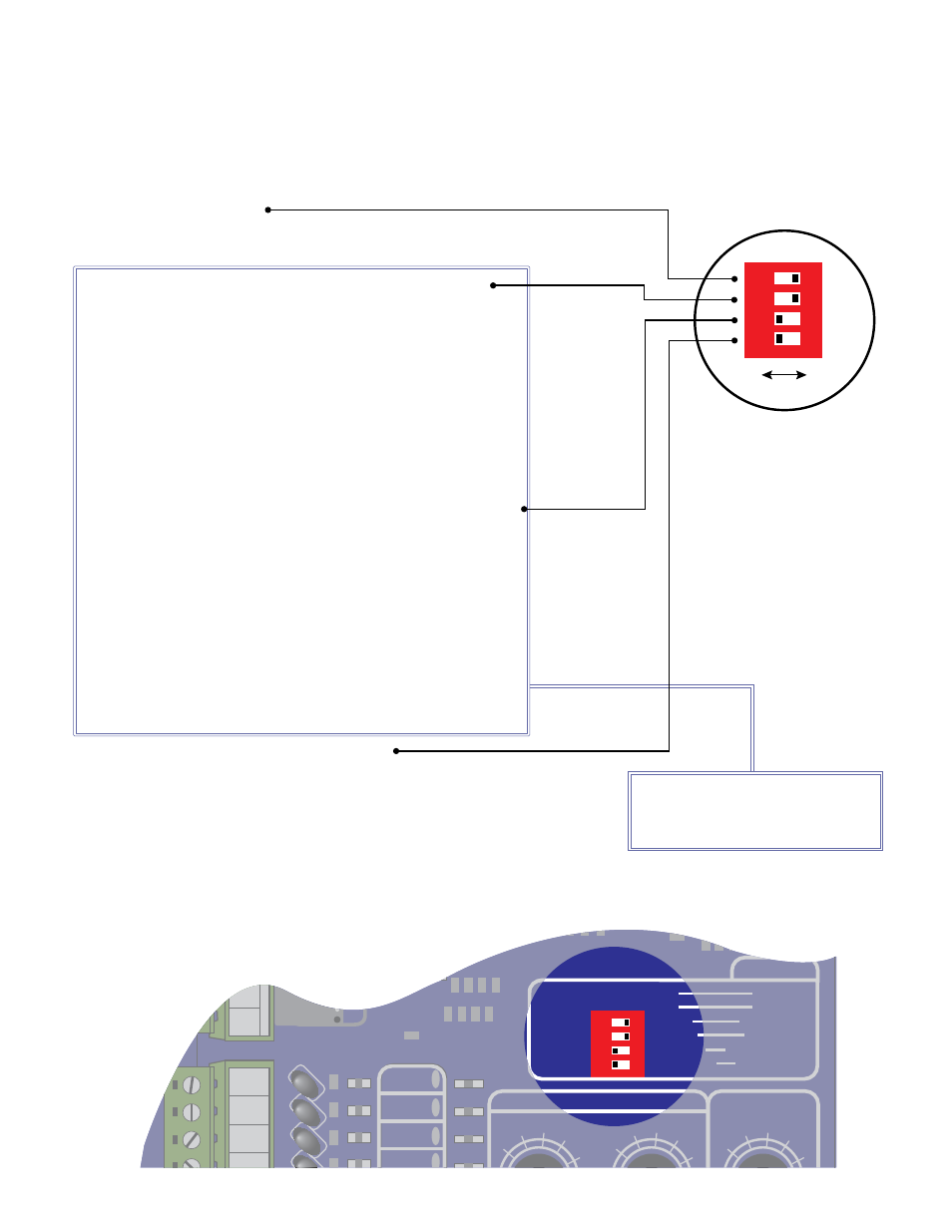
DiP switch settings
MODE 1 & MODE 2:
•
Reserved for future features
DIP #1: OPEN DIRECTION
•
OFF: for gate that opens to the left, closes to the right.
•
ON: for gate that opens to the right, closes to the left.
DIP #2: SLAVE OPEN SEQUENCE (dual gate installation only)
•
NOTE: This DIP switch is applicable if and only if all the
following conditions are valid:
•
DIP switch #3 is OFF (Master mode)
•
Dual Link cable is connected.
•
Slave mode is detected from the second board (DIP switch #3
of the second board is ON)
•
If the above conditions are not met, the board will default to
single gate operation. If DIP #3 is OFF (Master)
•
OFF: Slave gate will open after the master gate.
•
ON: Slave gate will open simultaneously with the master gate.
DIP #3: MASTER/SLAVE (applicable to dual gate installation only)
•
NOTE: This DIP switch is applicable if and only if all the
following conditions are valid:
•
Dual Link cable is connected.
•
The second operator is detected by the master.
•
If the above conditions are not met, the board will default to
single mode operation. If DIP #3 is OFF (Master)
•
OFF: Master mode operation in dual gate installation if slave
setting is detected from the other board.
•
ON: Slave mode operation in dual gate installation if master
setting is detected from the other board. Control board is non-
functional if master operator is not detected.
DIP #4: FAIL SAFE/FAIL SECURE OPERATION
•
OFF: Fail safe mode
When low battery and no AC power conditions are detected
the gate will automatically run to the opened position. The
gate will remain at the open position until AC power is restored
and the battery reaches an acceptable charge level.
•
ON: Fail secure mode
When low battery is detected and no AC power is present, the
gate will automatically run to the closed position. Gate will
auto close only if auto close feature is enabled and gate is at
open limit. The gate will remain at the closed position until AC
power is restored and the battery reaches an
acceptable charge level.
These switches are for dual gate
applications only. See page 26 for
dual gate settings.