Connecting the gate arm to the gate – GTO GP-SW050 User Manual
Page 18
15
Bolts
and
Washers
Reducer
Arm
Key
Closed Gate
Closing
Gate Bracket
Operator Arm
Reducer Arm
(approx)
5°-10° Angle
Clevis Pin
Hairpin Clip
Output Shaft
Fig. 1
Fig. 2
Fig. 5
Fig. 6
Fig. 4
CAUTION:
DO NOT STAND
IN THIS AREA
Fig. 3
1
2
3
4
O
N
OPTIONS
MODE 1
MODE 2
OPEN DIR.
SLV OPN
DUAL MODE
LOW BATT
ON
ON
>>>
SIMUL
SLAVE
SECURE
OFF
OFF
<<<
DELAY
MASTER
SAFE
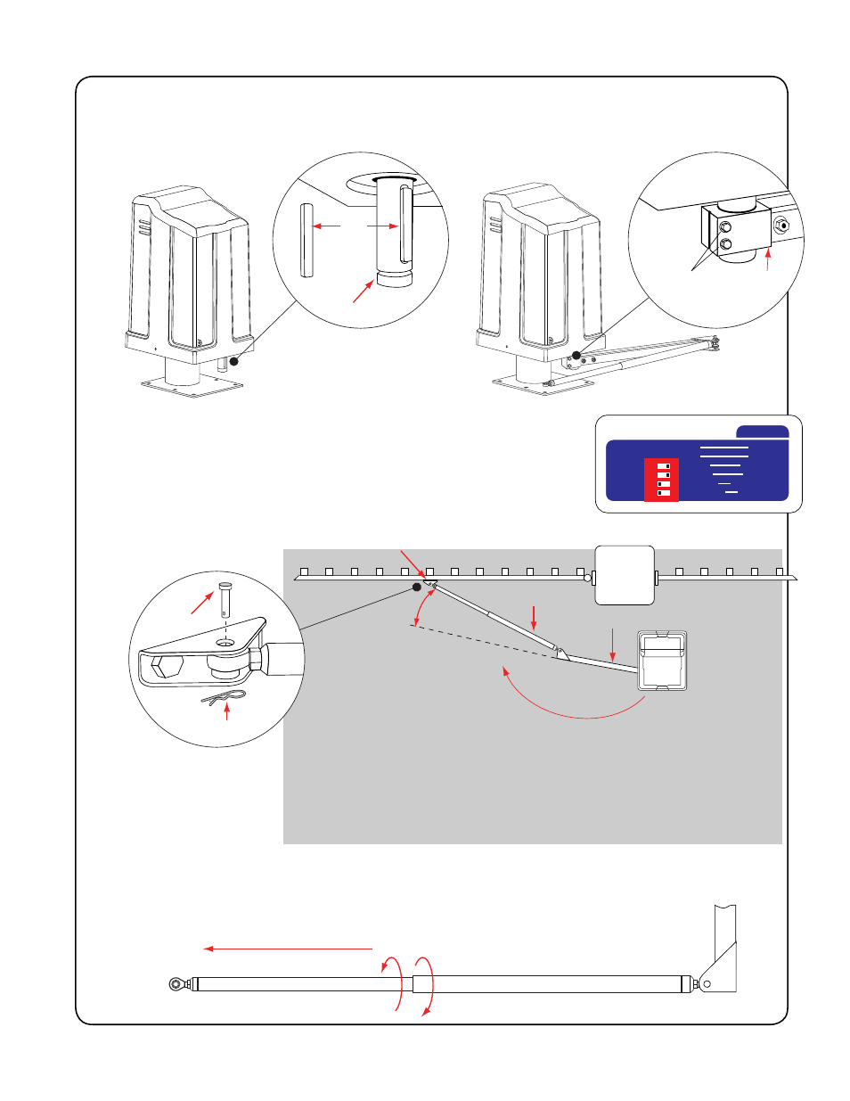
connecting the gate arm to the gate
NOTE: Gate Arm’s length can be adjusted
by rotating the gate arm’s tube before
mounting it to the gate bracket.
(Fig. 5)
1. Install the key into the output shaft. (Fig. 1)
2. Fit the end of the reducer arm onto the output shaft as shown and
tighten the bolts. (Fig. 2)
3. Turn the power on.
4. Set DIP switch 1 to designate the operator arm as left or right (Fig. 3)
(right is shown here).
5. Manually move gate to the closed position. (Fig. 4)
6. Unfold the arm to approximately a 5-10° angle. (Fig. 4)
7. Use ‘CLOSE’ button on control board to move operator arm/reducer arm to the gate. CAUTION: Be careful
not to stand in the gray area surrounding the operator. (Fig. 4) Be prepared to stop (using the ‘STOP’ button)
when the gate arm and reducer arm near the desired position.
NOTE: Use ‘JOG’ buttons to fine tune the position.
8. Mark the position of the gate bracket holes on the gate, drill holes and mount bracket.
9. Fit the end of the operator arm into the gate bracket and attach using clevis pin and hairpin clip. (Fig. 5)