Control board description – GTO GP-SW050 User Manual
Page 19
16
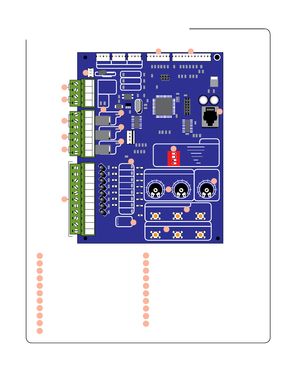
control Board Description
1
2
3
4
O
N
LOCK
COM
COM
COM
ALARM
CYCLE
SAFETY
SHADOW
OPEN
CLOSE
STOP
OPEN
EDGE
CLOSE
EDGE
STATUS
STALL FORCE ADJUST
LIMIT ADJUSTMENTS
DUAL
LINK
GTO LOOP DETECTORS
LIMIT SENSORS
DIAG.
PORT
BLDC SPEED CONTROL
EXIT SHADOW SAFETY
AT OPEN
LIMIT
PRISON
MODE
RUNNING
OPTIONS
TEST SWITCHES
CLOSE
STOP
OPEN
GTO Inc. Tallahassee, FL
SX4000 Logic Board Rev. E
MIN
MAX
MIN
MAX
OFF
120
<<< JOG >>>
<<< >>>
SET
LIMIT
CLOSED
+ ACC. PWR.
12VDC
- 300ma
W1
CUT TO USE
3 BUTTON
STATION
AUTO CLOSE
TIMER
MODE 1
MODE 2
OPEN DIR.
SLV OPN
DUAL MODE
LOW BATT
ON
ON
>>>
SIMUL
SLAVE
SECURE
OFF
OFF
<<<
DELAY
MASTER
SAFE
A
C
C.
PO
WER
DU
AL C
ABLE
+12Vdc
COM
DUAL LINK
LINK COM
REL
AY OUTPUT
S
LOCK N.C.
LOCK COM
LOCK N.O.
RUN 1
RUN 2
CLOSED 1
CLOSED 2
CYCLE
SAFETY
OPEN EDGE
CLOSE EDGE
OPEN
CLOSE
STOP
COM
COM
COM
SHADOW
LOOP
1
2
3
9
10
11
12
13
14
20
21
19
17
15
18
4
5
6
7
8
16
CO
M
+12V OPEN CO
M
CO
M
+12V OPEN CO
M
CO
M
+12V OPEN CO
M
BLDC Motor Control Connection
Limit Sensor Connection
Alarm / Buzzer Connection
12Vdc Accessory Power
Dual Link Connection
Relay Output - To Control Lock
Relay Output - To Indicate Gate’s Running
Relay Output - To Indicate Gate’s Closed
Accessory Inputs
LED Indicators - For accessory inputs
LED Indicators - To show ‘closed’ relay is on
1
2
3
4
5
6
7
8
9
10
11
LED Indicator - To Show ‘Running’ Relay is on
LED Indicator - To Show ‘Lock’ Relay is on
LED Indicators - To Show Dual Link Communication
Test Switches - To Control Gate Operation
Limit Adjustment Control Switches
Left and Right Stall Force Adjustment
Auto Close Timers Adjustment Potentiometer (OFF, 3-120 sec)
DIP Switch Option Setting
Diagnostic Port (NOT for telephone)
W1- for 3-button Station with Normally Close ‘Stop’ Button
12
13
14
15
16
17
18
19
20
21