Connector specifications, Appendix – FUJITSU DESKPOWER 6000 User Manual
Page 95
85
Appendix
○
○
○
○
○
○
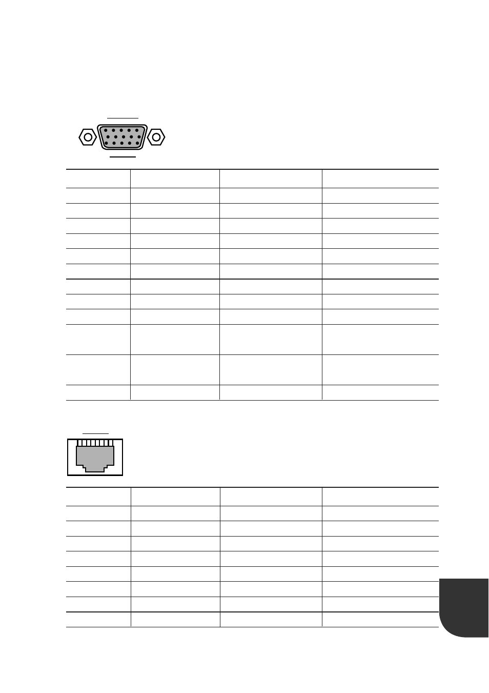
Connector specifications
The pin arrangement and signal names of each connector are as follows:
●
Display connector
5
1
15
10
6
11
Pin no.
1
2
3
4
5 to 8
9
10
11
12
13
14
15
Signal name
RED
GREEN
BLUE
NC
GND
+5V
GND
NC
SDA
HSYNC
VSYNC
SCL
Direction
Ouput
Output
Output
–
–
–
–
–
Input/output
Output
Output
Input/output
Description
Red output
Green output
Blue output
Not connected
Ground
+5V
Ground
Not connected
Data
Horizontal
synchronous signal
Vertical
synchronous signal
Data clock
●
LAN connector (100BASE-TX/10BASE-T)
1
8
Pin no.
1
2
3
4
5
6
7
8
Signal name
TD+
TD–
RD+
NC
NC
RD–
NC
NC
Direction
Ouput
Output
Input
–
–
Input
–
–
Description
Send data+
Send data–
Receive data+
Not connected
Not connected
Receive data–
Not connected
Not connected
See also other documents in the category FUJITSU Computers:
- T2000 (30 pages)
- SPARC ENTERPRISE M3000 (212 pages)
- PRIMERGY RX600 S6 (134 pages)
- BS2000 (37 pages)
- BX900 S1 (144 pages)
- BX900 S1 (142 pages)
- PRIMEQUEST 1000 Series C122-E119EN (109 pages)
- T5120 (26 pages)
- SPARC ENTERPRISE M9000 (560 pages)
- DESKPOWER 2000 (50 pages)
- SPARC M4000 (376 pages)
- ServerView Respurce Orchestrator Virtual Edition V3.1.0 (247 pages)
- PRIMERGY MX130 S2 (256 pages)
- SPARC ENTERPRISE T5120 (58 pages)
- T5240 (28 pages)
- M4000 (310 pages)
- SPARC M4000/M5000 (76 pages)
- TX150 S3 (95 pages)
- SPARC T5220 (240 pages)
- M9000 (518 pages)
- ServerView Resource Orchestrator Cloud Edition V3.1.0 (180 pages)
- PRIMERGY BX600 S2 (173 pages)
- FR family 32-bit microcontroller instruction manuel CM71-00101-5E (314 pages)
- M Server M4000 (30 pages)
- Primergy RX200 S2 (307 pages)
- DESKPOWER P301 (56 pages)
- SPARC Enterprise Server M4000 (62 pages)
- SPARC M8000 (4 pages)
- PRIMERGY B120 (68 pages)
- C120-E361-04EN (36 pages)
- R630 (76 pages)
- 2000 (66 pages)
- T1000 (84 pages)
- Server TX200 S6 (126 pages)
- PRIMERGY BX600 S3 (164 pages)
- SPARC ENTERPRISE T5220 (34 pages)
- SPARC M3000 (56 pages)
- TX300 (122 pages)
- PRIMERGY BX600 (288 pages)
- SPARC Enterprise Server M3000 (8 pages)
- SPARC Enterprise Server M3000 (202 pages)
- T850 (18 pages)
- T5440 (212 pages)
- Service View Resource Orchestrator Cloud Edition V3.0.0 (102 pages)