Block diagram area – AJA KONA 4 PCI-E Video I/O Card (HDMI Output, Cable Included) User Manual
Page 28
KONA Capture, Display, Convert v15.5 28 www.aja.com
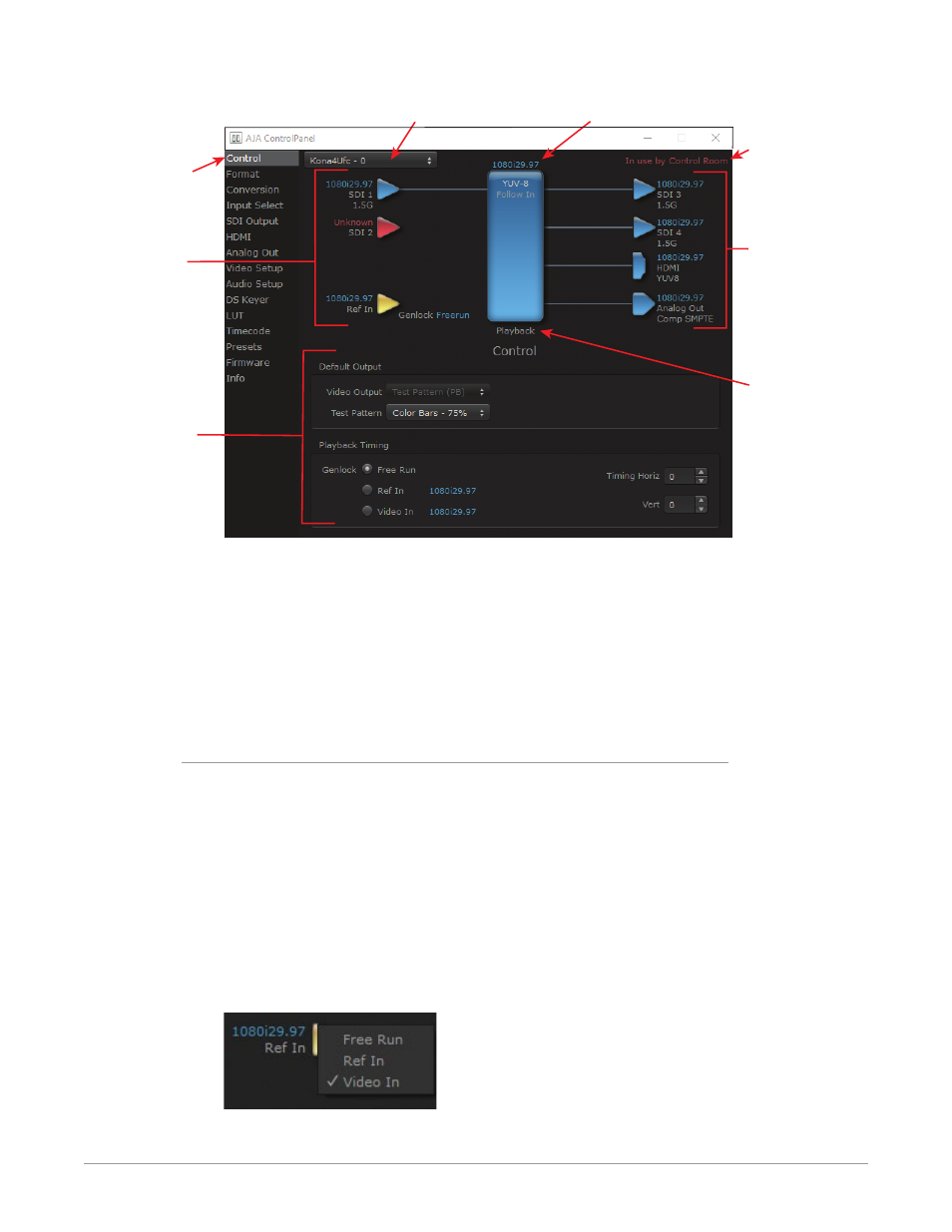
Figure 20. AJA Control Panel, Block Diagram and Controls
Inputs
Device Format (Framebuffer)
AJA Device Selection
Controlling
Application
Operating
Mode
Outputs
Currently
Selected
Function Screen
Parameter
Controls
Some controlling applications can switch the card's mode from Playback to
Capture, and vice-versa. When Control Panel is not being controlled by an
external application, you can change the operating mode in the Control Panel
Control Screen using the Default Output settings.
• Selecting Passthrough (Cap) sets the card to Capture Mode
• Selecting either Test Pattern (PB) or Hold Last App sets the card to Playback
Mode
See
for more information
Block Diagram Area
The top block diagram area of the Control Panel screen is a visual representation
of the processing, if any, that’s currently occurring, including inputs/outputs,
reference source, and system status. Lines between inputs, the framebuffer, and
outputs, show a video path. Where there are no lines, there is no connection; this
can be because an input or output isn’t selected in the Input Select menu. The
lines will also show whether the outputs are video or video + key.
NOTE: If a KONA card's SDI output BNC is available, that card's output signal will be
routed to that extra BNC, providing two identical SDI output signals.
You can click any of the function screen selection links in the left column to view
its current settings or click on an icon to call up its related settings screen. You can
also right-click or Control-click to see context-sensitive information and choices.
Figure 21. Context Sensitive Menu