AJA KONA 4 PCI-E Video I/O Card (HDMI Output, Cable Included) User Manual
Page 21
KONA Capture, Display, Convert v15.5 21 www.aja.com
In the KONA 5 system example above operating in 4K Mode, a single link 12G-SDI
camera signal is received by the KONA 5 card, sent to a 12G-SDI video production
switcher, and simultaneously downconverted to 3G-SDI for recording to a digital
VTR.
1. If desired, connect your house reference sync to the KONA 5 Ref BNC on the
card (labeled "R"). This is a terminated reference input.
2. Connect an HDMI monitor to the KONA 5 card's HDMI output connector.
3. Connect the 9-pin machine control cable on the supplied breakout cable to
your VTR’s RS-422 control port.
4. Connect the KONA 5's SDI 1 BNC to the SDI output of the camera, using one
of the provided mini-to-full size BNC adaptor cable provided.
5. Connect the KONA 5's SDI 3 BNC to the production switcher. This will
provide the full 12G signal received by the KONA card to the switcher.
6. Connect the KONA 5's SDI 4 BNC to the input an HD SDI digital video
recorder. This will provide a downconverted camera signal to the recorder.
7. Connect an HDMI or SDI monitor directly to an output of the digital video
recorder. Eight or sixteen channels of embedded audio are supported, so
the VTR must be configured accordingly.
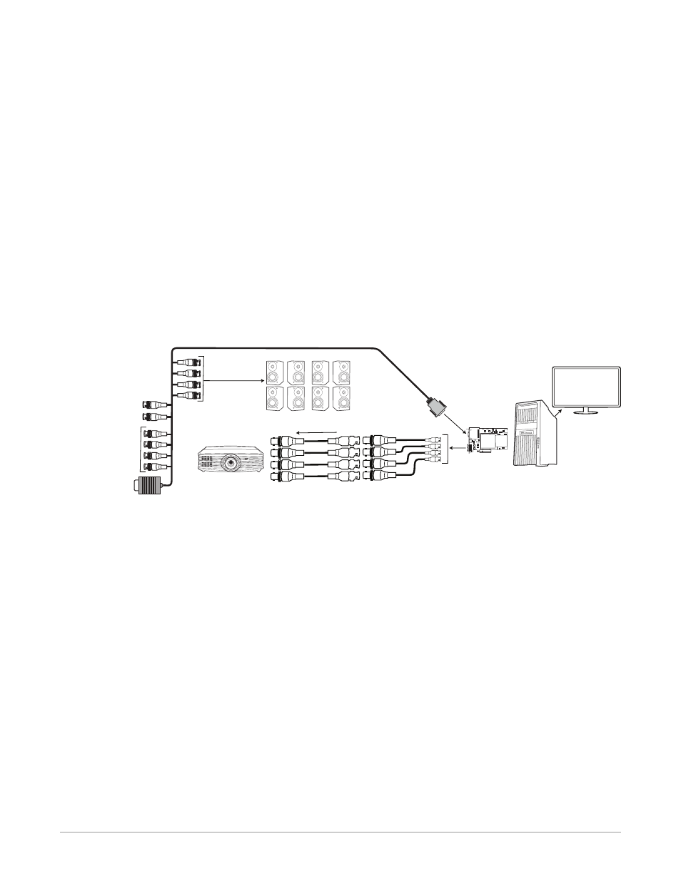
Figure 15. Typical KONA 5 System Connections, 8K Mode
BNC Adapter
SDI cables
Multi-pin KONA
Card Connector
1
2
Computer
Monitor
Workstation
Computer with
AJA Control Room
KONA 5 Card
(in computer)
3
4
4x 12G-SDI Video
8K Cinema Projector
PA System
LTC Output BNC
(not used)
LTC Input BNC
(not used)
AES Audio Input
BNCs Ch1-8
(not used)
RS-422
AES Audio Ouput
BNCs Ch1-8
(2 channels/
connector)
In the KONA 5 system example above operating in 8K Mode, an 8K ProRes video
file is played back with the AJA Control Room application, and sent to a cinema
projector using four 12G-SDI signals. Eight channels of AES embedded audio from
that file are also routed to the facility PA system.