Fcc compliance statement – ARRI ALEXA Mini LF Ready to Shoot V-Mount Set (LPL) User Manual
Page 131
Appendix
131
Following Art. 3.1 b,
2014/30/EU:
EN 301 489-1 V2.1.1
EN 301 489-17 V3.1.1
EN 55032:2015
EN 55035:2017
Art. 3.2
EN 300 328 V2.1.1
Essential Requirements regarding No 2:
EN 50581:2012
To evaluate the respective information, we used:
Year of affixed CE-marking: 2019
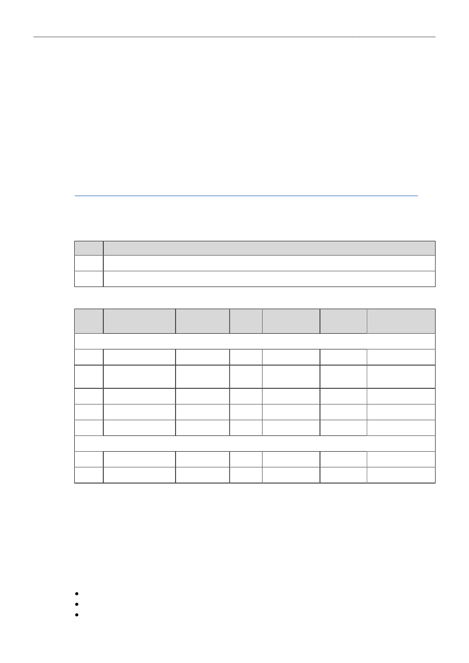
APPENDIX I - List of Primes
Item
Model Name
1
ARRI Signature Primes with Lens Data System 2 with focal lenght 18-280 mm
2
PL-to-LPL Adapter + ARRI Lenses with Lens Data System 1
APPENDIX II - List of Antennas
Item
Manufacturer
Model Name
Gain
(dBi)
Radiation
Pattern
Type
Connector
For ECS White Radio RF Module EMIP400s:
1
Nearson
S131AM-2450S
2.0
Omni-directional
Dipole
Reverse SMA
2
Proant
333 (Ex-it 2400
Foldable)
2.0
Omni-directional
Dipole
Reverse SMA
3
Radial/Larsen
R380.500.125
2.0
Omni-directional
Dipole
Reverse SMA
4
Wanshih
WSS002
2.0
Omni-directional
Dipole
Reverse SMA
5
Taoglas
GW26.0151
1.8
Omni-directional
Monopole
Reverse SMA
For WiFi 2.4 GHz RF Module ST60-2230C:
6
Radial
R380.500.150
0.0
Omni-directional
Monopole
Reverse SMA
7
LAIRD
LSR/001-009
2.0
Omni-directional
Dipole
Reverse SMA
FCC Compliance Statement
Class B Statement:
This equipment has been tested and found to comply with the limits for a Class B
digital device, pursuant to part 15 of the FCC Rules. These limits are designed to provide reasonable
protection against harmful interference in a residential installation. This equipment generates, uses and
can radiate radio frequency energy and, if not installed and used in accordance with the instructions,
may cause harmful interference to radio communications. However, there is no guarantee that
interference will not occur in a particular installation. If this equipment does cause harmful interference
to radio or television reception, which can be determined by turning the equipment off and on, the user
is encouraged to try to correct the interference by one or more of the following measures:
Reorient or relocate the receiving antenna.
Increase the separation between the equipment and receiver.
Connect the equipment into an outlet on a circuit different from that to which the receiver is
connected.