2 blink codes for loop controllers, 3 communications checklist – Heat Controller Water Source Heat Pump User Manual
Page 97
WattMaster WHP
Section 4
Start-Up and Troubleshooting
4-15
4.2
Blink Codes for Loop Controllers
The Loop Controller uses an on board LED to indicate various diagnostic conditions
during powerup and operation. The Loop Controller Unit LED is labeled “LED2”.
Starting with power up the LED blink codes are as follows:
•
Off for five seconds
•
COMM LED blinks the board address (Address 14 = 14 blinks)
•
Five second pause
•
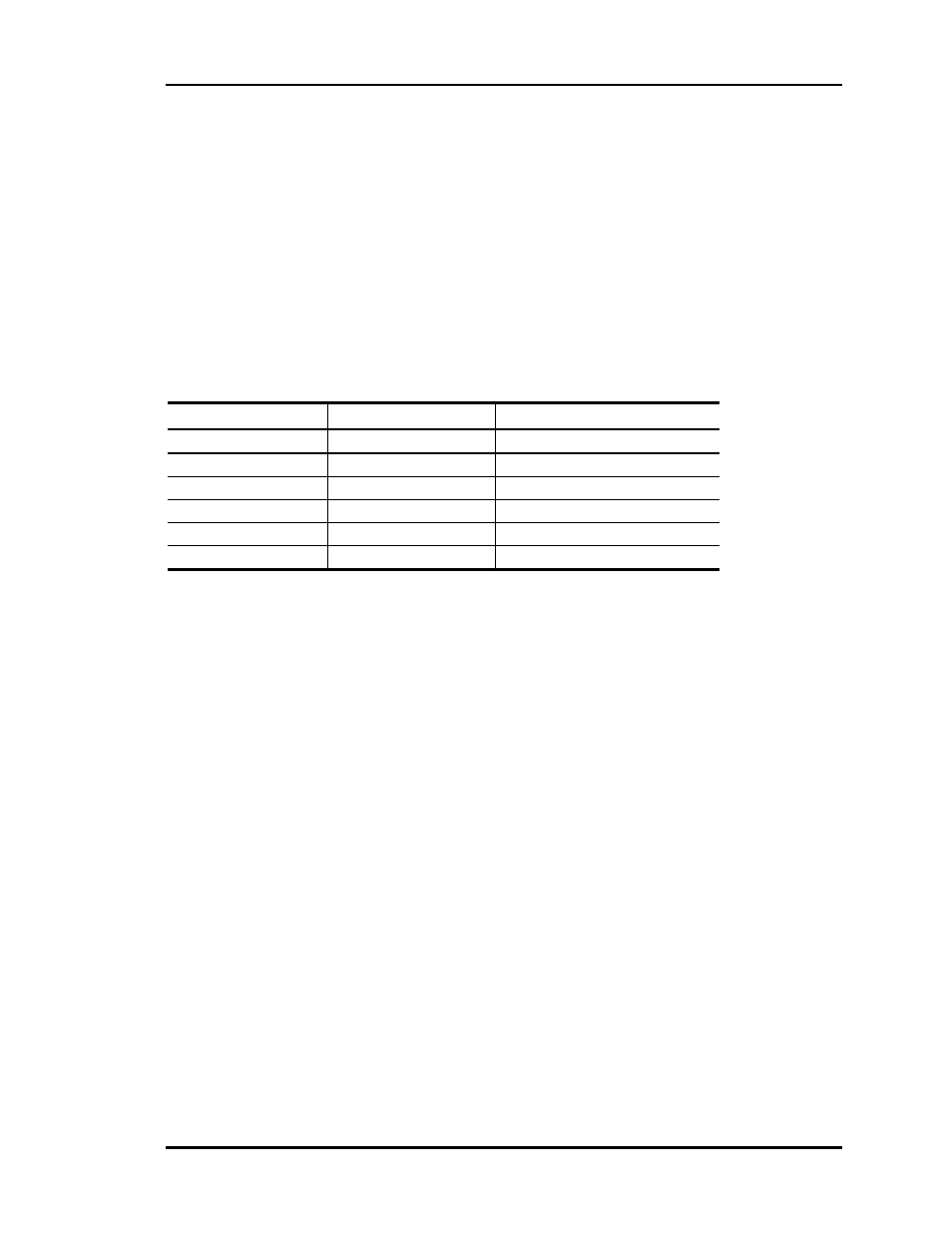
Status code is repeatedly blinked every ten seconds to indicate controller
status:
Priority
No. of Blinks
Status
Lowest
1
Normal Operation
-
2
Pump and/or Flow Failure
-
3
Bad Water Temp Sensor
-
4
Single Phase Shutdown
-
5
Water Pressure Alarm
Highest
6
Fire Alarm
Figure 4-7: Diagnostic LED Blink Codes
Only the highest priority failure code will be shown. You must correct the highest priority
alarm before other problems will be indicated.
4.3
Communications Checklist
•
WHP Controllers are addressed from 1 to 30 on each loop except the loop with the
WHP Loop Controller. This loop can only use address 1 thru 29 for the WHP Con-
trollers. WHP Loop Controller is addressed as 30 on the loop it is connected to.
•
Power has been cycled after changing addresses
•
A multiple loop CommLink II is powered and connected to the communications loop.
•
System Manager is connected to one of the local loops.
•
The MiniLinks on each local loop are addressed with a unique address 1 thru 30,
depending on the number of loops on your system.