3 checking the commlink ii driver – Heat Controller Water Source Heat Pump User Manual
Page 108
WattMaster WHP
Section 4
4-26
Start-Up and Troubleshooting
5.3.3
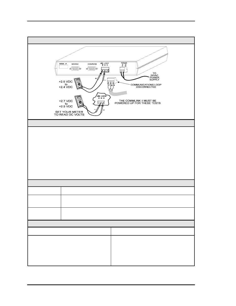
Checking the CommLink II Driver
Diagram
Overview
This test checks for proper Network loop voltages coming from the CommLink II.
Tip: The Loop LED (located on the front panel) should “flicker” when the CommLink II is
attempting to communicate. The Loop LED will flicker more noticeably for a few
seconds when first powered up. If the LED does not flicker, the unit is not function-
ing.
Proper loop voltages are essential for reliable communications. It is normal to see fluctua-
tions at this point on the CommLink II. The average value should be close to the acceptable
range described below. Values will vary upon initial powerup for about 10-15 seconds as
the unit attempts to communicate.
Measurements
Local Loop
Acceptable Range
T – G
(SHLD)
2.4 - 2.5 Volts DC
R – G
(SHLD)
2.5 - 2.7 Volts DC
Action
Condition
Action
If voltages are too high or too low on either
side
1. The CommLink II has a damaged comm
driver chip. Replace the driver chip.
See instructions in section 1.3.11 for
“Comm Driver Chip Replacement”.
2. The CommLink II is defective.