2 becoming familiar with the whp controller, 1 24 vac power connector, Warning – Heat Controller Water Source Heat Pump User Manual
Page 87: Figure 4-3: whp controller component layout
WattMaster WHP
Section 4
Start-Up and Troubleshooting
4-5
2.2
Becoming Familiar with the WHP
Controller
RELAY
OUTPUT
COM
1-3
OUT
OUT
1
2
COM
4-5
OUT
OUT
OUT
3
4
5
24VAC
GND
PWR
COMM
T
SHLD
LD4
REC.
12V
AIN
1
2
3
4
5
GND
GND
AOUT
AIN
AIN
AIN
AIN
4-5
OUT
COMM
TEST
32K
8K
RAM
EPROM
ADDRESS ADD
PRESSURE
SENSOR
485
COMM
R
YS101564
E
W
D
O
G
0-
5
VD
C
0-
1
VD
C
DIAGNOSTIC BLINK
CODE LED
ADDRESS SWITCH
( ADDRESS 18 SHOWN )
EPROM
PIN 1
INDICATION
RAM
RAM SIZE
SELECT JUMPER
PAL
REAL TIME
CLOCK CHIP
24VAC
POWER
INPUT
POWER LED
COMMUNICATIONS
DRIVER CHIP
COMMUNICATIONS
LED
ANALOG INPUTS
STATIC PRESSURE
SENSOR INPUT
RS-485
COMMUNICATIONS
LOOP
CPU
Space Sensor
Slide Adjust
Supply Air Temp
Leaving Water
Temp or
Dirty Filter
Lockout
24 VAC Common for Inputs 1 - 3
Compressor-On/Off (Heat 2)
Heat Pump Reset (Cool 1)
Aux. Heating or Cooling (Cool 2)
Rev. Valve-On/Off (Heat 1)
Fan-On/Off
24 VAC Common for Inputs 1 - 3
Mounting Backplate
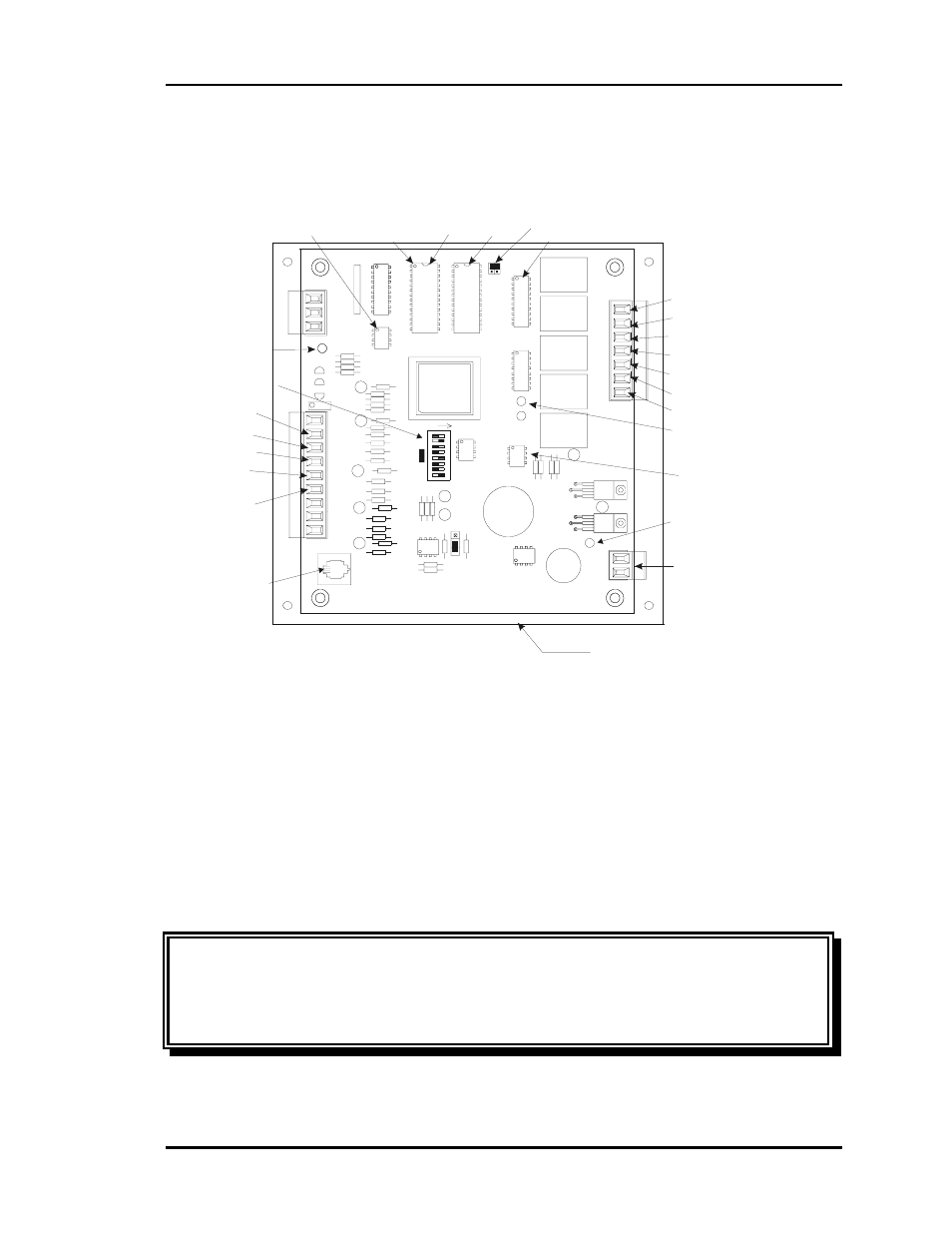
Figure 4-3: WHP Controller Component Layout
2.2.1
24 VAC Power Connector
This connector provides power to the WHP Controller.
24VAC - The “hot” side of the control transformer.
GND - The grounded side of the control transformer. If the secondary of the con-
trol transformer is not grounded, you must still observe polarity if the trans-
former powers any other device!
Warning:
Connect only the GND terminal to the grounded side of a transformer
- Failure to properly observe polarity will result in
damage to the system. Observe polarity at all points in the
system.