6 pressure sensor voltage chart – Heat Controller Water Source Heat Pump User Manual
Page 124
WattMaster WHP
Section 4
4-42
Start-Up and Troubleshooting
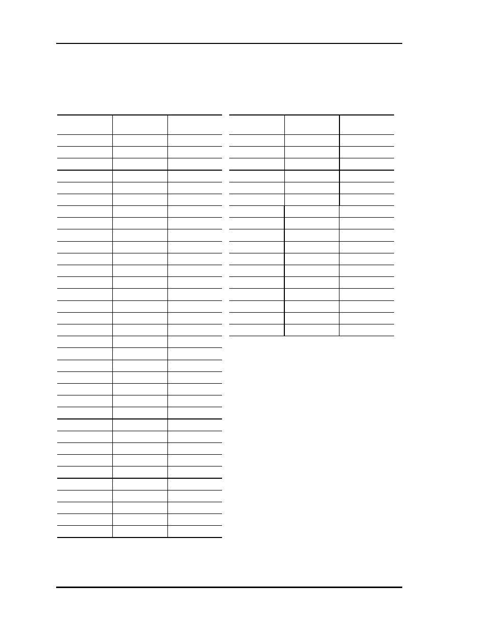
5.6 Pressure Sensor Voltage Chart
PRESSURE
PSI
CURRENT
MILIAMPS
VOLTAGE AT
INPUT
VDC*
0
4.00
1.00
1
4.32
1.08
2
4.64
1.16
3
4.96
1.24
4
5.28
1.32
5
5.60
1.40
6
5.92
1.48
7
6.24
1.56
8
6.56
1.64
9
6.88
1.72
10
7.20
1.80
11
7.52
1.88
12
7.84
1.96
13
8.16
2.04
14
8.48
2.12
15
8.80
2.20
16
9.12
2.28
17
9.44
2.36
18
9.76
2.44
19
10.08
2.52
20
10.40
2.60
21
10.72
2.68
22
11.04
2.76
23
11.36
2.84
24
11.68
2.92
25
12.00
3.00
26
12.32
3.08
27
12.64
3.16
28
12.96
3.24
29
13.28
3.32
30
13.60
3.40
31
13.92
3.48
32
14.24
3.56
33
14.56
3.64
PRESSURE
PSI
CURRENT
MILIAMPS
VOLTAGE AT
INPUT
VDC*
34
14.88
3.72
35
15.20
3.80
36
15.52
3.88
37
15.84
3.96
38
16.16
4.04
39
16.48
4.12
40
16.80
4.20
41
17.12
4.28
42
17.44
4.36
43
17.76
4.44
44
18.08
4.52
45
18.40
4.60
46
18.72
4.68
47
19.04
4.76
48
19.36
4.84
49
19.78
4.92
50
20.00
5.00
*Notes:
1.
Use the voltage column to compare the
meter voltage with the sensor connected to
the controller and with the controller pow-
ered.
2.
Read voltage with meter set on DC volts.
Place the “-”(minus) lead on GND terminal
and the “+”(plus) lead on the sensor input
terminal being investigated.
3.
If the voltage is less than 0.05 VDC, then
the sensor or wiring is “shorted” or “open”