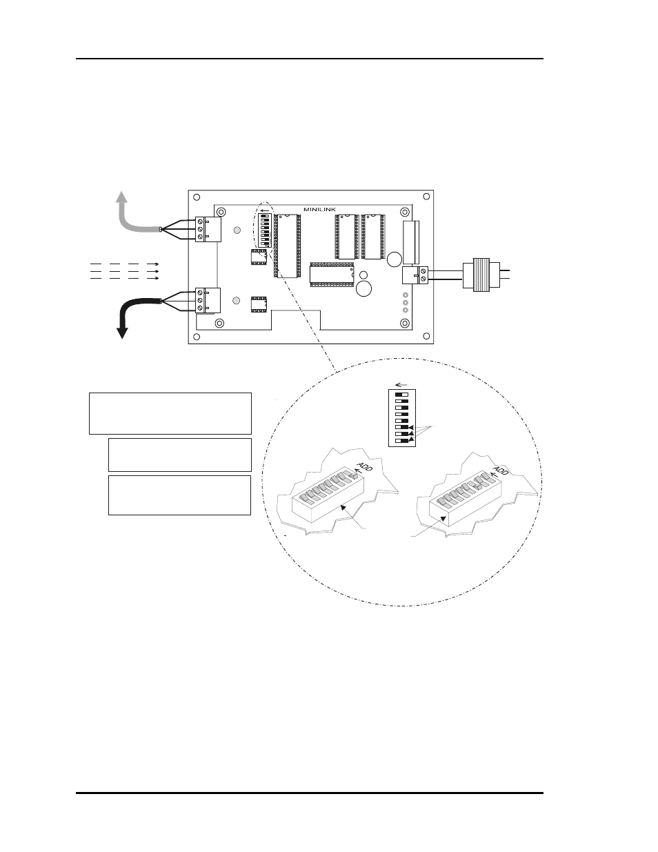
Minilink addressing, Figure 2-13: minilink address switch setting, Minilink communications interface – Heat Controller Water Source Heat Pump User Manual
Page 42
Section 2
WattMaster WHP
2-18
Installation and Wiring
MiniLink Addressing
Notes:
R
SH
T
R
SH
T
R
SH
T
R
SH
T
All Communication Loop
Wiring Is Straight Through
16
32
8
4
2
1
Caution!
The MiniLinks Must Have Address Switches Set Between 1
And 30 (Up To 30 MiniLinks Are Allowed Per WHP System
System). The MiniLinks Should Be Addressed In
Consecutive Order Starting With Address #1. Address #1
Must Be Present On The Loop For The System To Function.
Address Switch Shown Is
Set For Address 1
Address Switch Shown Is
Set For Address 4
MiniLink
Address Switch
These Switches Must Be
In The OFF Position
As Shown
Required VA For Transformer
MiniLink = 6VA Min.
See Note 1.
Note:
The Power To The MiniLink Must Be Removed And
Reconnected After Changing The Address Switch
Settings In Order For Any Changes To Take Effect.
Caution:
Disconnect All Communication Loop Wiring
From The MiniLink Before Removing Power
From The MiniLink. Reconnect Power And Then
Reconnect Communication Loop Wiring.
ADD
The Address For Each MiniLink
Must Be Unique To The Other MiniLinks
On The Network Loop. Loop #1 MiniLink
Should Be Addressed As #1
Loop #2 MiniLink Should Be Addressed
As #2 Etc..
24VAC
GND
T
SH
R
32
16
8
4
1
2
OFF >
Local Loop
RS-485
9600 Baud
Connect To Next
Controller or
System Manager
Connect To Next
MiniLink And/Or
CommLink On
Network Loop
Network Loop
RS-485
19200 Baud
Line Voltage
24VAC
MiniLink Communications Interface
1.)24 VAC Must Be Connected So
That All Ground Wires Remain
Common.
2.)All Wiring To Be In Accordance
With Local And National Electrical
Codes And Specifications.
3.) All Communication Wiring To Be
2 Conductor Twisted Pair With
Shield. Use Belden #82760 Or
Equivalent.
ADD
NETWORK
SH
T
R
LOOP
Figure 2-13: MiniLink Address Switch Setting