ProSoft Technology MVI56E-DNPNET User Manual
Page 110
Contents
MVI56E-DNPNET ♦ ControlLogix Platform
User Manual
DNPNET Ethernet Client/Server Communication Module
Page 110 of 140
ProSoft Technology, Inc.
February 13, 2015
Module Data Objects
These objects hold process and status data values. All supported DNPNET data types have
their own UDTs and controller tags. This makes it easier to identify and use the various data
types.
Read Block
READ Blocks transfer information from the module to the ControlLogix processor. The
following table describes the basic block structure of an input image.
Block Offset
Content
0
Reserved
1
Write block ID
2 to 241
Read data
242 to 248
Spare (Not used)
249
Read block ID
The Read Block ID is an index value used to determine the location of where the data will be
placed in the ControlLogix processor read data controller tag array. Each transfer can move
up to 240 words (block offsets 2 to 241) of data. The value of the Read Block identification
code indentifies the type of data contained in the block, so the sample ladder logic can move
it to the correct controller tag array.
The Write Block ID contained in the Read Block tells the ladder logic which block of data the
module is expecting to receive from the ControlLogix processor during the next backplane
transfer. Under normal program operation, the module sequentially sends read blocks and
requests write blocks. For example, if one block each of binary and analog output data, one
block of binary input data, two blocks of counter data and two blocks of analog input data
are used with the application, the backplane transfer sequence block numbers will be:
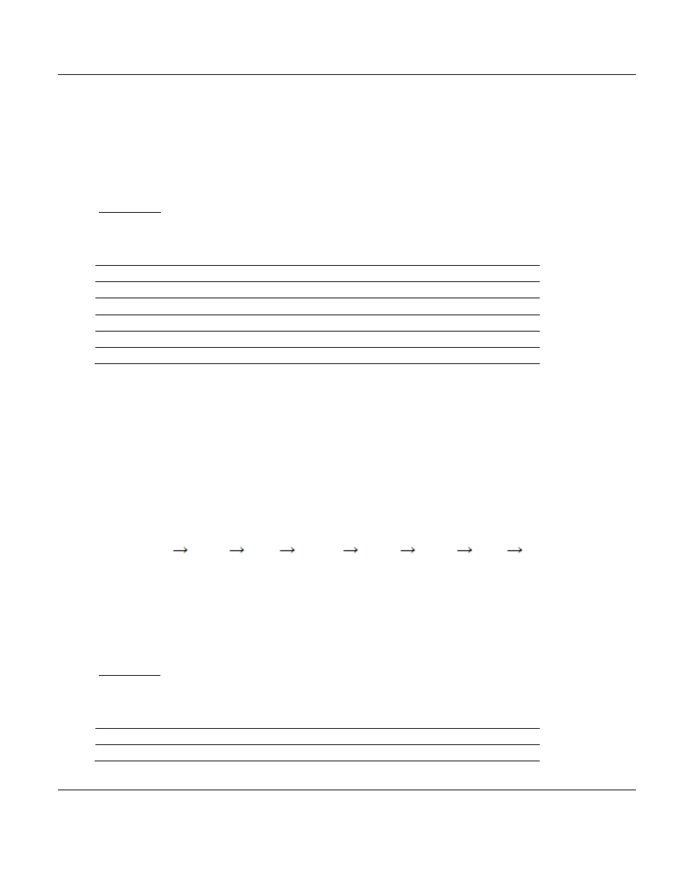
R4W0
R16W8
R4W9
R16W12
R4W13
R16W0
R4W8
This sequence will continue until interrupted by other write block numbers sent by the
controller or by a command request from a node on the DNPNET network or operator
control through the module’s Configuration/Debug port. This sequence is occasionally
interrupted by the read block identification code 100. This block passes the error/status and
error list information from the module to the processor. Refer to the Error/Status section of
this document for the structure and data contained in a Status Read block.
Write Block
WRITE blocks transfer information from the ControlLogix processor to the module. The
following table describes the structure of a typical output image Write Block.
Block Offset
Content
0
Write block ID